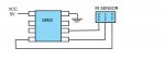
IR sensor to 08M2
- Thread starter Shocker
- Start date
westaust55
Moderator
Can you please provide a link to the datasheet for the Sharp IR sensor.
Also please post your schematic diagram showing how you have connected (and what capacitors you have included)
plus your code that you have tried to date.
What remote device are you using to activate the IR sensor?
Also please post your schematic diagram showing how you have connected (and what capacitors you have included)
plus your code that you have tried to date.
What remote device are you using to activate the IR sensor?
http://sharp-world.com/products/device/lineup/data/pdf/datasheet/gp2y0d810z_e.pdf
Schematic required - e.g. you have connected pin1-3 and resistor on pin 2 etc. etc.
Schematic required - e.g. you have connected pin1-3 and resistor on pin 2 etc. etc.
westaust55
Moderator
It may also be warranted to have a read of this thread for what I believe is the same IR sensor device (Sharp IR rangefinder GP2Y series):
http://www.picaxeforum.co.uk/showthread.php?10933-pwmout-not-behaving-as-expected
http://www.picaxeforum.co.uk/showthread.php?10933-pwmout-not-behaving-as-expected
westaust55
Moderator
No resistor! Ouch!Will check thread. I didn't add resistors as it functions normally when connected directly to VCC and ground. View attachment 13156
In what way is it working?
The resistor is used to control/limit the current through the IR LED.
With Resistor = 4.3 Ohms the current is 70 mA. With no resistor it will be higher still.
A PICAXE output can only supply a maximum of 20 mA / Absolute maximum of 25 mA without damage to the PICAXE chip.
Do you have the link between pins 1 and 3 as mentioned by Technical at post2?
Do you have the two 0/1 uF capacitors at pins 11 and 7 as per the datasheet?
Do you have decoupling capacitors for the PICAXE 08M2?
How are you controlling the Vin signal at pin 12?
Can you please post a complete schematic diagram showing how you have all pins on the IR ranging sensor connected.
Re. SAborn:
Supplying both seemed odd to me to, I tried it with common ground with no luck, the diagram was just a variation I thought might work (it didn't).
Re. westaust55:
The technical post is outlining the IR sensor circuitry, all resistors and caps are there as in the block diagram from the factory. the sensor has three outputs (OUT, VIN AND GND). The current through the IR measured at just over 5 mA as stated in the data sheet which I believe is within the 08M2 parameters. It seemed like it should be able to plug in directly, but that doesn't appear to be the case. With the IR powered by VCC directly it works, and the signal out will trigger the PIC pin high or low as it should.
westaust55
Moderator
The pin Vin is not an output but an input signal. Taking that pin high enables the output. Taking pin Vin low puts the IR module into standby mode.
Gnd is neither input nor output, it is a reference line for the other signals.
It would still be good if you could post a schematic diagram of exactly what you have. Draw a diagram in MS Paint and save in .jpg mode if you have no other software.
Where exactly have you measured the 5 mA?
Gnd is neither input nor output, it is a reference line for the other signals.
It would still be good if you could post a schematic diagram of exactly what you have. Draw a diagram in MS Paint and save in .jpg mode if you have no other software.
Where exactly have you measured the 5 mA?
Last edited:
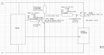
As outputs I meant lines out, I know what the Vin and ground do. I measured the Amps at the ground and at Vcc and here is a diagram as it stands right now.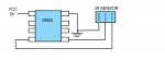
The program "HIGH 2" (not really even a program) is dead simple for testing, i just want power at pin 2 to see if the IR is being powered (it has a built in led to indicate it's active).
The program "HIGH 2" (not really even a program) is dead simple for testing, i just want power at pin 2 to see if the IR is being powered (it has a built in led to indicate it's active).
westaust55
Moderator
Pin 2 of the IR module is the IR LED feedback resistor connection - the resistor you did not fit.i just want power at pin 2 to see if the IR is being powered
Please, please, please provide us with a proper schematic diagram so we know how you have your project wired.
your descriptions are not always aligned with the datasheet and making more confusion. Otherwise we will go around in circles for another 50 posts.
I will be away form the forum for a while going to an appointment so lets see what you can provide in the next couple of hours.
Last edited:
Note i increased the value of R1 to 15R in the schematic thinking the led was supplied from the picaxe it is not, its only triggered by the picaxe, so you can decrease R1 to 4R3 or there abouts, or the sensing distance might be reduced.
Without R1 the IR chip may be damaged, so please include it as Westy has told you to previous.
Without R1 the IR chip may be damaged, so please include it as Westy has told you to previous.
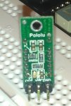
Okay, bear with me, the diagram in post #11 is the schematic, here is an image of it on breadboard.
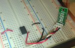
The sharp data sheet shows the detailed schematic of the IR. As far as I can see I have 3 wires coming out of the IR and 8 pins on the 08M2, I assume that the IR circuit has the necessary resistors and caps on board for it to function with an IC. Does this help or do you need more info?
The sharp data sheet shows the detailed schematic of the IR. As far as I can see I have 3 wires coming out of the IR and 8 pins on the 08M2, I assume that the IR circuit has the necessary resistors and caps on board for it to function with an IC. Does this help or do you need more info?
I'm not sure if Westy and SABorn realise you are using a PCB with some gubbins already on it.
Is this the one?
http://www.pololu.com/catalog/product/1133
(I seem to be doing Ec's job for him!!") )
)
If so it would have really helped if you'd posted the info in Post Number 1.
Always supply the bulk of the info as soon as you ask the question.
Is this the one?
http://www.pololu.com/catalog/product/1133
(I seem to be doing Ec's job for him!!
)If so it would have really helped if you'd posted the info in Post Number 1.
Always supply the bulk of the info as soon as you ask the question.
Okay, bear with me, the diagram in post #11 is the schematic, here is an image of it on breadboard.
The sharp data sheet shows the detailed schematic of the IR. As far as I can see I have 3 wires coming out of the IR and 8 pins on the 08M2, I assume that the IR circuit has the necessary resistors and caps on board for it to function with an IC. Does this help or do you need more info?
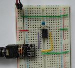
The 08M in the photo needs much more to
function correctly.
Serin grounding, capacitor, ......
e
See
Manual 1, p. 44
A simplified, but non-programmable method,
is to insert say a 1000 Ohm resistor
between Serin (leg 2) and ground.
And capacitor?
0.1 microFarad ( aka 100 nanoFarad)
as close as possible between
V+ gnd ( legs 1 and 8)
IMHO,
the best for breadboarding,
is the AXE029
with a 100nF added
e
Attachments
-
 108.8 KB Views: 15
Time wasting i think, where a little better information could have saved several of us much effort, and resulted in far better advice.I'm not sure if Westy and SABorn realise you are using a PCB with some gubbins already on it.
Same for the picaxe setup, where a few moments spent reading the manuals would provide a good understanding, without the need to spoon feed information.
westaust55
Moderator
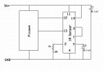
here is the schematic for that pololu IR sensor module as Dippy had identified from the photo showing the links, capacitors and LED current control feedback resistor being enquired about are part of the plug in module.
Certainly good to know this information up front by links to the sensor module were more than just a basic component is involved.
What was provided at post 1 and 5 were block diagram which over simplified the circuit in the absence of full information.
Certainly good to know this information up front by links to the sensor module were more than just a basic component is involved.
What was provided at post 1 and 5 were block diagram which over simplified the circuit in the absence of full information.
Attachments
-
 52.3 KB Views: 28
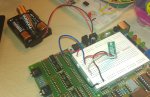
My apologies, IR came as one unit didn't realize that the serial number didn't cover the accompanying circuit board. I have tried this on the AXE091 board which I believe has the necessary caps and resistors built in to run the PIC. I have run an led off of the PIC to make sure it is putting 2 high, no problem led lights up. The IR sensor (sharp and pololu) will not come on though.
Photo and program please.My apologies, IR came as one unit didn't realize that the serial number didn't cover the accompanying circuit board. I have tried this on the AXE091 board which I believe has the necessary caps and resistors built in to run the PIC. I have run an led off of the PIC to make sure it is putting 2 high, no problem led lights up. The IR sensor (sharp and pololu) will not come on though.
e
westaust55
Moderator
If you still have it wired as per your block diagram in post 5, then you must also have a LOW 1 since you have the IR sensor module Gnd conenction to the 08M(2) IO pin1.
remember that all birectional IO are set up as inputs on powr up for the newer (M2 and X2) PICAXE chips.
Why don't you just connect the IR sensor Gnd pin directly to the supply ground - saves a little on volt drop to the IR sensor and saves a PICAXE IO pin.
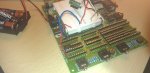
Now looking at your photos it seems you have done just that but the IR sensor output is not connecting back to the PICAXE.
Is the LED on the IR sensor module coming on to indicate voltage to the IR Sensor module is present?
How are you trying to determine if the IR sensor is working if code is limited to HIGH 2 ?
remember that all birectional IO are set up as inputs on powr up for the newer (M2 and X2) PICAXE chips.
Why don't you just connect the IR sensor Gnd pin directly to the supply ground - saves a little on volt drop to the IR sensor and saves a PICAXE IO pin.
Now looking at your photos it seems you have done just that but the IR sensor output is not connecting back to the PICAXE.
Is the LED on the IR sensor module coming on to indicate voltage to the IR Sensor module is present?
How are you trying to determine if the IR sensor is working if code is limited to HIGH 2 ?
When IR is connected to VCC and ground an LED on the back lights up when an object is in range, so I'm looking for the same reaction when hooked to pin 2. I have had the sensor output wired to pin 3 -while using Vcc and Ground- to "trigger" an LED (pin 1) and it worked as expected, so I'm just focusing on the power issue.
westaust55
Moderator
From the schematic at post 22, there is a red LED which is energised when the power is applied (in your case when pin2 is taken high) AND the output is low.
Is that the LED you are talking about? or is there one on the GP2Y IR module on the pololu module?
From the datasheet that technical reference in post 2, the when the output is high (ie the red LED will be off) the voltage will be Vcc - 0.6 V so about 3.9 volts if you are running on 3 x AA batteries as per your earlier photo.
When the LED comes on, the output is low and the Vout signal is about 0,6 volts so the PICAXE will see a LOW state = 0 (zero).
From page 5 of the datasheet the output is low when the object is in the range 20mm to approx 100 mm otherwise the output is high
Last edited:
westaust55
Moderator
Okay that sounds/read good.
So where exactly is the problem?
at post 25 you stated:
HIGH 2
DO
IF pin1 = 0 THEN
b5 = 0
ELSE
b5 = 1
ENDIF
DEBUG ; or SERTXD (#b5, cr, lf)
LOOP
So where exactly is the problem?
at post 25 you stated:
So if you have the output connected to say PICAXE pin1 (physical leg 6) then using program line(s) such asAs I said previously 2 is set high and will power an LED but the IR won't turn on.
HIGH 2
DO
IF pin1 = 0 THEN
b5 = 0
ELSE
b5 = 1
ENDIF
DEBUG ; or SERTXD (#b5, cr, lf)
LOOP
The problem is, if I run this program
MAIN:
HIGH 1
IF PINC.2 = 1 THEN HIGH 4
ELSE LOW 4
END IF
GOTO MAIN
The IR will not work if IR Vin is connected to pin 1, however if I put Vin to Vcc it works fine. Pin 1 does go high (I ran an LED off it to check it) just doesn't seem to be able to power the IR, but from the data it seems like it should work. I must be missing something.
westaust55
Moderator
I still believe that the PICAXE pin is being overloaded.
See my comments back at post 7.
Your Pololu module has a 4.3 Ohm resistor for the IR LED so there are current pulses to 70mA.
Vin[/sub\ as you call it is the supply for the entire IR module you are not switching just the Vin/enable signal.
I recommend you try using an NPN plus PNP transistor as a high side switch controlled by the PICAXE and see if that resolves your problem. I can post a schematic for this in an hour or so if you need one.
Last edited:
westaust55
Moderator
Okay, I lied , it was more than an hour , but attached is a schematic showing how to use two transistors as a high side switch.
This is based on a BC548 transistor and a BC558 transistor plus a few resistors.
, it was more than an hour , but attached is a schematic showing how to use two transistors as a high side switch.This is based on a BC548 transistor and a BC558 transistor plus a few resistors.
Attachments
-
 186.6 KB Views: 18
inglewoodpete
Senior Member
You need a 0v reference for the output of the IR module, so that the PICAXE senses the IR output value correctly. If you use low-side switching, the 0v point on the module is raised to VCE of the (NPN) transistor being used.
If using a common 4.5 to 5.0 volt supply rail for both the PICAXE and the IR module, you could get away with just a high-side PNP transistor. But not an NPN on its own.
If using a common 4.5 to 5.0 volt supply rail for both the PICAXE and the IR module, you could get away with just a high-side PNP transistor. But not an NPN on its own.
I can see no good reason why you would want to switch the IR module on or off in circuit anyway, what is to be gained from doing this?
If its to conserve power (i still dont see why) then why not make a small change the sensor board circuit and use the sensor enable pin, as the sensor was designed to work with for this application.
In reality if the sensor is powerd from the supply rails, so when the picaxe is on the sensor is on, then it should not matter as you can choose when to read the data and when not to.
westaust55
Moderator
The two transistor approach is more universal and easily adapted to those times when the "load" requires a voltage higher than the PICAXE supply. For heavier load current just change the PNP transistor (eg BC328 for 800 mA) and recalc a resistor or two.Is there a reason you prefer the transistor pair over a single transistor?
The reason for the two transistors is that a high side switch needs a PNP however to turn it off, the base must rise to very close to the load supply voltage. If say the load voltage is 6 V for a servo or motor, etc the PICAXE cannot raise an output above its supply voltage ( max 5V) so the PNP would not turn off. Hence the NPN to allow the PNP base to be pulled high enough by the resistor to the load supply rail.
If you want a 1 transistor approach when the PICAXE and load are fed from the same voltage (as in you current project) then you can omit the NPN transistor.