westaust55
Moderator
Digital Potentiometers
Digital potentiometers can in general be used in place of mechanical potentiometers.
Applications are wide and varied and include amplifier gain/volume control, variable oscillator control and even a for of DAC (digital to analogue) to, for example, achieve an analogue output in a PICAXE circuit.
Many IC manufacturers including Microchip, Maxim and Analog Devices all manufacture digital potentiometers.
The PICAXE range of chips include digital inputs, digital outputs, analogue inputs but no analogue outputs.
By using a digital potentiometer, a basic analogue output can be achieved.
Microchip offerings:
Microchip manufacture a range of digital potentiometers. Some of the prime considerations are:
- Overall resistance (typical ohmic values are 2.1k, 5k, 10k, 50k and 100k)
- Number of steps/taps over the total resistance range( common values are 64 and 256)
- Method of control (up/down or serial data via SPI and occasionally via i2c comms)
- Number of potentiometers in a single package
- Whether the Digital Pots have volatile or non-volatile memory (to remember the setting after power removal).
Below are notes on a few of the different offerings from Microchip including the method of control. All of the devices covered below are of the volatile type and so lose their settings when the power is removed.
MCP4011
The MCP4011 is an 8-pin SOIC package with a single digit potentiometer which is controlled using the up/down approach with an operating voltage range of 2.7V to 5.5Vdc.
The MCP4011 is one of a series (MCP4011/2/3/4) and can in fact be configured externally to implement the configurations of the other three digital pots in the series.
Note that the absolute maximum current through the potentiometer or thought any on of the pot pins is 2.5mA.
The three potentiometer pins (A, B and W) are not polarity sensitive but must be between Vss and Vdd.
Internally, the wiper has a resistance (Rw) of 75 ohms
When the MC4011 is powered-up, the default setting is the mid-point tap/setting. This has an internal wiper setting value of $1F (dec 31).
Two pins are used to control the MCP4011 chip, being CS and U/D.
CS Pin
The chip select pin, CS, is used to control whether the chip accepts serial commands.
When the CS pin is high, the digital potentiometer does not respond to commands.
When the CS pin is low, the digital pot responds to step commands on the U/D pin
U/D Pin
The U/D pin is used firstly to set the increment or decrement mode and secondly to subsequently step the pot wiper on subsequent rising edges of the signal to the U/D pin.
The MCP4011 also has a high voltage serial command mode for compatibility with the MCP402x range of digital pots but this mode is not covered here.
Operation
When the CS pin is taken low to commence a change in pot wiper position, the voltage level on the U/D pin at the time the CS pin is taken low determines whether the increment or decrement mode is selected.
The increment/Decrement protocol enables the potentiometer to move one step at a time through the range of possible resistance values. The pot wiper value does not roll over, underflow or overflow.
If the U/D pin is high when the CS pin is taken low, then this sets the “direction” for step but does not cause a step of the pot wiper. If the CS pin is then retained in a low state, subsequent rising edges on the U/D pin cause the pot wiper to increment. This moves the wiper one step towards terminal A. The maximum wiper setting value when the wiper is at terminal A is $3F. Once the internal pot wiper value reaches $3F, subsequent increment pulses are ignored.
If the U/D pin is low when the CS pin is taken low, then subsequent rising edges on the U/D pin cause the pot wiper to decrement. This moves the wiper one step towards terminal B. The minimum wiper setting value when the wiper is at terminal B is $00. Once the internal pot wiper value reaches $00, subsequent decrement pulses are ignored.
If one reads the datasheet it will be noted that:
1. There is differential error between increment and decrement modes – this means you may not achieve the same resistance between the end terminals and the wiper at a given wiper position when you reach that position when stepping from the A and B terminals to that position.
2. There is some non-linearity between the resistance steps. With a 5.5V supply this is typically 0.25 of the LSb.
3.The wiper resistance can vary significantly with voltage and temperature.
Timing considerations
For the MCP4011, the minimum duration for most characteristics in the timing waveforms is 500nsec.
With a PICAXE at 4MHz or 8MHz operation, this duration will typically not require any further delays. I have tested at both 4MHz and 8Mhz and not needed any delays or longer pulses. However, if the PICAXE is operated at higher clock speeds, it may be found necessary to incorporate a brief pause (for example PAUSE 1 or PAUSEUS 50) to ensure the required timing waveforms are achieved.
A PICAXE program:
Enough theory on the MCP4011 so lets use a small program to control the MCP4011 and step it up and down through the 64 wiper positions.
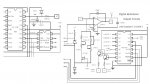
Firstly, I have assumed that the MCP4011:
- is the 10 kOhm resistance rating (ie MCP4011-103)
- has the “A” terminal is connected to 5Vdc (=Vdd) and the B terminal is connected to 0Vdc (=Vss). In this way, the increment mode will result in an increasing voltage at the wiper terminal as the program increments each step.
Based upon the above assumptions, the wiper step number and the nominal output voltage at the wiper terminal are also displayed via the SERTXD command on the PC's terminal screen (use F8 in the programming Editor to access the Terminal screen and set it to 4800 baud)
For indicative purposes, I used a 45mm analogue meter with a scale of 0 to 50uA (coil resistance 3000 Ohms).
By using a 100K Ohm and 3.3 MOhm resistor in parallel (equates to ~97kOhm) all in series with the meter, the meter is effectively calibrates 0 to 5 Volts.
Thus the scale 0 to 50 uA represents 0 to 5.0 Volts.")
If the pauses in the above program example are removed, the output appears to slowly but smoothly swing back and forth between 0V to 5V and back to 0V ad infinitum at a rate of ~6 seconds per cycle with a clock speed of 4MHz
Digital potentiometers can in general be used in place of mechanical potentiometers.
Applications are wide and varied and include amplifier gain/volume control, variable oscillator control and even a for of DAC (digital to analogue) to, for example, achieve an analogue output in a PICAXE circuit.
Many IC manufacturers including Microchip, Maxim and Analog Devices all manufacture digital potentiometers.
The PICAXE range of chips include digital inputs, digital outputs, analogue inputs but no analogue outputs.
By using a digital potentiometer, a basic analogue output can be achieved.
Microchip offerings:
Microchip manufacture a range of digital potentiometers. Some of the prime considerations are:
- Overall resistance (typical ohmic values are 2.1k, 5k, 10k, 50k and 100k)
- Number of steps/taps over the total resistance range( common values are 64 and 256)
- Method of control (up/down or serial data via SPI and occasionally via i2c comms)
- Number of potentiometers in a single package
- Whether the Digital Pots have volatile or non-volatile memory (to remember the setting after power removal).
Below are notes on a few of the different offerings from Microchip including the method of control. All of the devices covered below are of the volatile type and so lose their settings when the power is removed.
MCP4011
The MCP4011 is an 8-pin SOIC package with a single digit potentiometer which is controlled using the up/down approach with an operating voltage range of 2.7V to 5.5Vdc.
The MCP4011 is one of a series (MCP4011/2/3/4) and can in fact be configured externally to implement the configurations of the other three digital pots in the series.
Note that the absolute maximum current through the potentiometer or thought any on of the pot pins is 2.5mA.
The three potentiometer pins (A, B and W) are not polarity sensitive but must be between Vss and Vdd.
Internally, the wiper has a resistance (Rw) of 75 ohms
When the MC4011 is powered-up, the default setting is the mid-point tap/setting. This has an internal wiper setting value of $1F (dec 31).
Two pins are used to control the MCP4011 chip, being CS and U/D.
CS Pin
The chip select pin, CS, is used to control whether the chip accepts serial commands.
When the CS pin is high, the digital potentiometer does not respond to commands.
When the CS pin is low, the digital pot responds to step commands on the U/D pin
U/D Pin
The U/D pin is used firstly to set the increment or decrement mode and secondly to subsequently step the pot wiper on subsequent rising edges of the signal to the U/D pin.
The MCP4011 also has a high voltage serial command mode for compatibility with the MCP402x range of digital pots but this mode is not covered here.
Operation
When the CS pin is taken low to commence a change in pot wiper position, the voltage level on the U/D pin at the time the CS pin is taken low determines whether the increment or decrement mode is selected.
The increment/Decrement protocol enables the potentiometer to move one step at a time through the range of possible resistance values. The pot wiper value does not roll over, underflow or overflow.
If the U/D pin is high when the CS pin is taken low, then this sets the “direction” for step but does not cause a step of the pot wiper. If the CS pin is then retained in a low state, subsequent rising edges on the U/D pin cause the pot wiper to increment. This moves the wiper one step towards terminal A. The maximum wiper setting value when the wiper is at terminal A is $3F. Once the internal pot wiper value reaches $3F, subsequent increment pulses are ignored.
If the U/D pin is low when the CS pin is taken low, then subsequent rising edges on the U/D pin cause the pot wiper to decrement. This moves the wiper one step towards terminal B. The minimum wiper setting value when the wiper is at terminal B is $00. Once the internal pot wiper value reaches $00, subsequent decrement pulses are ignored.
If one reads the datasheet it will be noted that:
1. There is differential error between increment and decrement modes – this means you may not achieve the same resistance between the end terminals and the wiper at a given wiper position when you reach that position when stepping from the A and B terminals to that position.
2. There is some non-linearity between the resistance steps. With a 5.5V supply this is typically 0.25 of the LSb.
3.The wiper resistance can vary significantly with voltage and temperature.
Timing considerations
For the MCP4011, the minimum duration for most characteristics in the timing waveforms is 500nsec.
With a PICAXE at 4MHz or 8MHz operation, this duration will typically not require any further delays. I have tested at both 4MHz and 8Mhz and not needed any delays or longer pulses. However, if the PICAXE is operated at higher clock speeds, it may be found necessary to incorporate a brief pause (for example PAUSE 1 or PAUSEUS 50) to ensure the required timing waveforms are achieved.
A PICAXE program:
Enough theory on the MCP4011 so lets use a small program to control the MCP4011 and step it up and down through the 64 wiper positions.
Firstly, I have assumed that the MCP4011:
- is the 10 kOhm resistance rating (ie MCP4011-103)
- has the “A” terminal is connected to 5Vdc (=Vdd) and the B terminal is connected to 0Vdc (=Vss). In this way, the increment mode will result in an increasing voltage at the wiper terminal as the program increments each step.
Based upon the above assumptions, the wiper step number and the nominal output voltage at the wiper terminal are also displayed via the SERTXD command on the PC's terminal screen (use F8 in the programming Editor to access the Terminal screen and set it to 4800 baud)
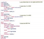
Code:
; =================================================
;   File....... MCP4011 digital Potentiometer test program
;   Purpose....
;   Author..... Westaust55
;   E-mail.....
;   Started.... 17-12-2009
;   Updated....
; =================================================
;
; -----[ Program Description ]---------------------------------------------
;
; A program to demonstrate the PICAXE control of the MCP4011 digital potentiometer
; the program starts at the default mid position, steps down to the minimum/step 0
; position and then repeatedly cycles stepping to the max step ($3F) and back down
; to the mining step ($00) positions.
;
;
; -----[ Revision History ]------------------------------------------------
;
;
;; - - - - - - - - - - - - - - - - - - - - - - - - - - - - - - - - - - - -
;
; - - - - - - - - - - - - - - - - - - - - - - - - - - - - - - - - - - - -
;
; Define the PICAXE Digital Outputs
SYMBOL LCD    = 0			; assumes a serial LCD display is connected to PICAXE output pin0
SYMBOL CS     = 1			; the MCP4011 CS pin connects to PICAXE output pin 1
SYMBOL UD     = 2			; the MCP4011 U/D pin connects to PICAXE output pin 2
;
; - - - - - - - - - - - - - - - - - - - - - - - - - - - - - - - - - - - -
; Define variable alias names
SYMBOL wiper  = b1
SYMBOL mvolts = w1		; using a word for 0 to 5,000 millivolts
SYMBOL axefact = b4		; factor to prevent 16-bit maths overflow and improve accuracy
;
; - - - - - - - - - - - - - - - - - - - - - - - - - - - - - - - - - - - -
; Define constants
SYMBOL minpos  = $00 		; = 0  = setting for the min position at B terminal
SYMBOL maxpos  = $3F 		; = 63 = setting for the max position at A terminal
SYMBOL default = $1F 		; = 31 = default power up wiper position is at midpoint
SYMBOL magic   = $08		; magic number to prevent math overflow and improve accuracy
SYMBOL voltage = $05		; Power is 5Vdc regulated
;
; - - - - - - - - - - - - - - - - - - - - - - - - - - - - - - - - - - - -
; Define the initial conditions
Init:
	HIGH CS			;	set the chip select high to disable serial control.
	wiper = default

Main:
; decrement to the lowest resistance step = Terminal B
	LOW UD 			; set U/D pin to low state to indicate decrement mode
	LOW CS 			; set CS pin low to enable serial control of the MCP4011
	DO
		PULSOUT UD, 1		; 1 msec pulse on the UD line to step down
		wiper = wiper - 1 	;
		GOSUB CalcVolts		; calculate and display voltage
		PAUSE 2000		; wait 2 seconds before moving to the next step
	LOOP UNTIL wiper = $00	; loop until MCP4011 wiper is at B terminal
	HIGH CS	; Finished stepping down so must set CS pin high before can select a new mode.
;
; increment to the maximum resistance step = Terminal A
	HIGH UD ; set U/D pin to high state to indicate increment mode
	LOW CS ; set CS pin low to enable serial control of the MCP4011
	LOW UD ; this is not essential as the PULSOUT command actually toggles the pin involved
	DO
		PULSOUT UD, 1	; 1 msec pulse on the UD line to step up
		wiper = wiper + 1 ;
		GOSUB CalcVolts 	; calculate and display voltage
		PAUSE 2000		; wait 2 seconds before moving to the next step
	LOOP UNTIL wiper = $3F	; loop until MCP4011 wiper is at A terminal
	HIGH CS			; Finished stepping down so must set CS pin high before can select a new mode.
GOTO Main
;
;
; Subroutine to calculate voltage when there is 5V across the potentiometer "A" to "B" terminals
CalcVolts:
		axefact = 512
		IF wiper >0 THEN
			axefact = maxpos + 1 * magic / wiper
		ENDIF
		mvolts = wiper * 1000 / magic * axefact  / maxpos * voltage * magic / axefact

		;SEROUT LCD, N2400, (#mvolts, "mVolts")
		SERTXD ("step = ", #wiper,"  " ,#mvolts, "mVolts", CR, LF)
RETURNBy using a 100K Ohm and 3.3 MOhm resistor in parallel (equates to ~97kOhm) all in series with the meter, the meter is effectively calibrates 0 to 5 Volts.
Thus the scale 0 to 50 uA represents 0 to 5.0 Volts.
If the pauses in the above program example are removed, the output appears to slowly but smoothly swing back and forth between 0V to 5V and back to 0V ad infinitum at a rate of ~6 seconds per cycle with a clock speed of 4MHz
Last edited: