Yet Another Simple Logic Level Mosfet Problem...

K-Young

New Member
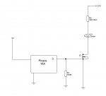
Alright, I'm sure there is a really easy explanation for this, but for some reason I'm having trouble with this very simple circuit. Before I decide to hook up a motor and play around with PWM, I wanted to see if I can drive the Logic Level Mosfet I got. So I hooked up the simple circuit I have shown in the schematic.

However, it does not work. The LED does not come on and the voltage that I measure on Pin 3 is about 0.63 volts. I know that the code is running since I set the pin to turn on and off every 5 seconds and it goes from 0.63V to 0.

The type of Logic Level Mosfet I'm using is a STP20NF06L.

Also, I'm using the Revolution programming board to do all this:

http://www.rev-ed.co.uk/docs/CHI030.pdf

Sorry if this has been asked and answered a hundred times. I did a quick search on the forums and I couldn't find anything that would help me out.

If it helps, I hooked the following circuit up without the PIC using a pushbutton switch instead and it worked:

http://brunningsoftware.co.uk/FET.htm
 

Attachments

Last edited:

premelec

Senior Member
It would seem that you have a wiring error or blown MOSFET as the gate input resistance should be VERY high and not load the PICAXE pin... disconnect the MOSFET 'gate' line and see if the pin goes from 0 to 5 volts as expected. And connect the MOSFET gate to 5v as a separate test of function. Could be a gate to drain short...
 

K-Young

New Member
It would seem that you have a wiring error or blown MOSFET as the gate input resistance should be VERY high and not load the PICAXE pin... disconnect the MOSFET 'gate' line and see if the pin goes from 0 to 5 volts as expected. And connect the MOSFET gate to 5v as a separate test of function. Could be a gate to drain short...
No, that doesn't help. The MOSFET seems to be fine.:confused:

I take away the Picaxe and apply 5V to the gate of the MOSFET, while keeping everything else essentially the same. LED comes on.
:mad:
 

Dave E

Senior Member
Are you sure that the 100k resistor is 100,000 ohms?
Test the Picaxe pin with nothing attached to see if it toggles between 5v and ground.

Dave E
 

K-Young

New Member
Are you sure that the 100k resistor is 100,000 ohms?
Test the Picaxe pin with nothing attached to see if it toggles between 5v and ground.

Dave E
Hmm, now this is interesting. I get the same thing with nothing connected, 0.63V. I was using Pin 3 and I tried pin 4, same thing. Does it have to do something with the ULN2803A?

Upon further inspection, the pin on the Picaxe seems to be toggling between 5V and zero, same with the input of the ULN2803A, but the output seems to be only 0.62V. So fried ULN2803A more than likely, or is there something else?

EDIT:

Actually running this program seems to work fine:

main: high 4
pause 1000
low 4
pause 1000
goto main

LED blinks on and off, so it can't be the ULN2803A
 
Last edited:

moxhamj

New Member
Where is the ULN2803? I can't see this in the original schematic, or maybe I missed something. Under certain circumstances you may not measure volts on a ULN2803 but it would depend on the schematic. Could you post that schematic and also maybe a quick photo?
 

K-Young

New Member
Where is the ULN2803? I can't see this in the original schematic, or maybe I missed something. Under certain circumstances you may not measure volts on a ULN2803 but it would depend on the schematic. Could you post that schematic and also maybe a quick photo?
It's right here, the exact same board I'm using:

http://www.rev-ed.co.uk/docs/CHI030.pdf

Now if you look on page 6 of the Picaxe manual found here:

http://www.rev-ed.co.uk/docs/picaxe_manual1.pdf

You'll see that the way you hook up things to the board does vary. The schematic on the left will not work, but the one on the right does. Judging from that, it looks like I hooked up the gate of the MOSFET directly to output 4, which will not work.

I don't know how else to do this...
 

lanternfish

Senior Member
Try driving the MOSFET directly from the picaxe pin, NOT the 2803. All the 2803 does is switch on an open collector transistor so its output only conducts to 0V.
 

K-Young

New Member
Try driving the MOSFET directly from the picaxe pin, NOT the 2803. All the 2803 does is switch on an open collector transistor so its output only conducts to 0V.
Yeah, I was thinking about that, but there has to be a better way, or else this development board is only good for making LEDs flash on and off:(

Any other suggestions, because I know your method will work.

So it's on the ouput side of the 2803, as page six of the manual I posted demonstrates.
 

MPep

Senior Member
I will second the suggestion to bypass the ULN2803.
These are an Open-Collector output, therefore they can ONLY drive LOW. What you need is something that will drive the gate HIGH. A direct connection to the PICAXE pin will take care of that.

I note you are gearing up to using PWM via MOSFET. In that case, you will need BJTs to drive the gate Hi and Lo. The BJTs can charge and discharge the gate capacitance FAST, which is important!
Something I am not certain of is how fast a logic MOSFET can work.
 

moxhamj

New Member
Well it would be a bit unorthadox, but if you already have a board, and you already have a mosfet...

The output of the ULN2803 switches between connecting to 0V, and floating. If it is at 0V then the mosfet will be off. If it is floating, then the mosfet will still be off. So you could try a 'pullup' resistor of 1k. Try connecting the ULN2803 to the gate of the mosfet, and the 1k resistor between the gate of the mosfet and 5V.

But the more standard way is just to connect the gate of the mosfet to the picaxe directly.
 

K-Young

New Member
Well it would be a bit unorthadox, but if you already have a board, and you already have a mosfet...

The output of the ULN2803 switches between connecting to 0V, and floating. If it is at 0V then the mosfet will be off. If it is floating, then the mosfet will still be off. So you could try a 'pullup' resistor of 1k. Try connecting the ULN2803 to the gate of the mosfet, and the 1k resistor between the gate of the mosfet and 5V.

But the more standard way is just to connect the gate of the mosfet to the picaxe directly.
So something like this:

http://i37.tinypic.com/egpbva.jpg
 

Dippy

Moderator
Yes, but REMOVE that 5V connection that goes to "3".
You could pop your PICAXE when the PICAXE output pin goes low. (i.e. 5V straight through PICAXE driver).

Driving MOSFETs depends very much on type of MOSFET. Simple on/off slow driving of a Logic level is fine direct, though a small resistor is recommended.
PWMing of a tiddler with lo current switching is probabaly OK too.

But PWMing a power MOSFET will require a driver for the Gate.
The 'Gate' of all MOFETs have capacitance. Tiddlers don't have much usually (the old BS170 had <40pF) . Big ones do - typically >>500pF.
Capacitance means charge. And you have to suck it out and shove it in as fast as possible for efficient switching.

Excellent drivers are available in DIP8 or SOIC8.

Standard Logic Level MOSFETs re usually driven just the same. It's just that the Gate voltage 'sensitvity' is more suited to 5V (or -5V) driving.
(Not to be confused with specialist MOSFET based devices which have logic/protection etc built in.)


PS
The old MOSFET chestnut crops up SO often can some guidance be added to any of the Manuals please?
Nothing too technical Technical :))) , just some guidlines and driver suggestions.
Then we can refer the 50 questions per annum to that page....
Now that hippy has sobered up post-birthday he can get typing and drawing :)
I've sent him a TTi PSU for his present so that should spur him on.
(There may be a delay due to Royal Mail strike though).
 
Last edited:

Dazza1964

New Member
It's right here, the exact same board I'm using:

http://www.rev-ed.co.uk/docs/CHI030.pdf

Now if you look on page 6 of the Picaxe manual found here:

http://www.rev-ed.co.uk/docs/picaxe_manual1.pdf

You'll see that the way you hook up things to the board does vary. The schematic on the left will not work, but the one on the right does. Judging from that, it looks like I hooked up the gate of the MOSFET directly to output 4, which will not work.


Hi if you look at that page on the manual and go up to point 4 you will see that it talks about the Darlington circuit is on the right and a normal circuit on the left.
This is my first post on this forum so please forgive any errors.
 

K-Young

New Member
Alright guys, thanks for all your advice but like many other solutions, the best one is usually the easiest. So I found an innovative way of bypassing the the ULN2803 by taking the chip up and running a jump wire across the socket of the IC. Everything worked like it should.

Also, the PWMing of the LED worked ok today(without the Mosfet Driver, but I have a couple laying around just in case), and I didn't seem to have any trouble. Tomorrow I'll actually hook up a small DC fan and see how that goes.

Thanks guys for all your help again, this is a great place for those just starting out.
 

MPep

Senior Member
Welcome to the forum Dazza.

K-Young: you're correct of course, the simplest way is usually the best. Or at least, if something is wrong, then it doesn't take too much to find the fault :D. I recommend using the MOSFET drivers. If you look at the specs, they have quite a high current rating to drive the gates.

I personally find the KISS priciple ("Keep It Simple, Stupid"!) the best. Or if you get offended easy then think of it as "Keep It Super Simple".

MPep.
 

Rickharris

Senior Member
Dippy, just to clarify in case others access this thread as the problem has been rectified,

I see your comment applies to the diagram the poster supplied but his diagram is incorrect, There is a darlington ic in there as well as this is a project board.

The correct change to impliment DrAculas suggestion is to remove the 100K resistor so the 1K pulls the MOSFET gate up to turn it on and th darlington output pulls it down to turn it off.

Just to clarify.

(If I am wrong I will delete this post - anyone agree?)
 
Last edited:

centrex

Senior Member
From what I can see the 2803 is a darlington open collector and would require a pullup resistor to plus 5 volts at the gate of the fet.

regards
centrex
 

MartinM57

Moderator
Yes, we are all sort of singing from the same hymn sheet:
- the 2803 is a darlington open collector device
- the normal way of driving a mosfet is to use a PICAXE output directly (via 100R or so, normally), where logic 1 turns the mosfet on
- the best way to do this with the project board is to take the 2803 out and link across the holder (that's not to say the project board is no good - it does what it (sort of) says on the tin and contains mutiple output drivers - they're just open collector drivers)

You could use a 2803 to pull down a pull high mosfet gate but:
- it's really a waste of a component
- the logic level is inverted - logic 1 from the PICAXE turns off the mosfet
- the 2803 is not a perfect switch to ground. It will pull the gate down to 0-6-1.2v only. You need to look at the mosfet data sheet to see if that implies anything about whether it starts conducting from drain to source in this condition
- with a pullup, you don't even need a darlington - just use a PICAXE output directly. Logic 1 re-inforces the pullup and keeps the mosfet on;logic 0 pulls down the gate to very close to 0v and turns the mosfet off.

As pointed out, if the schematic in post #1 had been accurate, we would have finished this thread 15 posts ago :)
 

Dippy

Moderator
Ah Rick, thats what we like: duff info. Great.

Rick you are absolutely right - apart from the fact that there is only one "o" in "lose".
(Two "o"s = my ex-wife ;) ).

Well, I got confused.
Was it with 2803 or were we going to bypass it ....?
Are we "gearing up to PWM" or are we just switching an LED.(Ell Eee Dee)?

Yes, with a 2803 a pullup is fine for simple slow stuff.
Direct driving from PICAXE (recommend a small res) is fine if slow or MOSFET weedy.
But none on the suggestions is ideal for efficient driving of power MOSFET for fast PWM.
- hence I threw in the driver.

All I'll say, as a general comment, is that the method of driving depends on your app, how FAT your MOSFET is and the voltages and loads involved. I've had enough of MOSFETs and suggesting people read the Data Sheets now ;)
 

BeanieBots

Moderator
Some logic level MOSFET have a gate threshold which is very close to the saturation voltage of a darlington driver. There may (in some circumstances for some FETs) be a significant FET leakage if used that way.

As Dippy says. Driving methods depends a lot on the specific application.
 
Top