Wierd pwming behavior

JTepper

Member
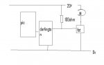
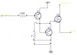
ok i have a BIG mosfet (irf1405n) connected to physical pin 12 of the picaxe (28x1 with 16mhz external resonator) via a darlington driver used to swich the 20v for the mosfet to turn on, and i can easily turn the motor on and off using the high portc 1 and low portc 1 commmands, but i cannot get pwm to respond in any way shape or form, eavy at 100% duty cycle there is no response from the pic, a multimeter between the pin and ground shows only 5 volts no matter what the duty cycle ( the pin is high by default because of the low sided switching of the mosfet, motors are off when pin is high)
SOS
 
Last edited:

Andrew Cowan

Senior Member
Correct pin?

Driver wired up correctly?

Note - you need to use a totempole driver - not just a darlington (on the FET gate).

A
 

JTepper

Member
totempole driver? please enlighten me

I'm pretty sure its wired up corretly because i can turn the motor on and off with no issues
 

manie

Senior Member
In my learning curve I've found that you MUST pull the FET gate down via a resitor or then better through a totem pole to realy ground and discharge the FET capacitance. Otherwise it tends to stay "half" on and gets VERY hot in the process. My 2c worth as noob.
 

Andrew Cowan

Senior Member
Darlington = either pulled high, or floating.

Floating = last state = high.

To pull it low, either use a resistor (as manie suggests), or a totempole driver (like in a PICAXE output - it is 0V or +V). If you go down the resistor path, use a 1K resistor. You need to pull it low fast.

I'm still worried you are putting 20V into that FET - 20V is the absolute maxmium allowed. 20.5V may not destroy the FET immediatly, but it will cause damage. Three or four silicon diodes will give about a 2.5V voltage drop - much healthier for the FET.

A
 

JTepper

Member
hadent even thought of the diodes for the mosfets, ill do that

heres how i was using the darlington, doesnt this pull it low, or otherwise high?
 

Attachments

manie

Senior Member
I would think something like in the schematic.

28x1 pin = high, Q1(pnp) = off, Q2 base =low, Q2 pulls Fet gate to 0V=off
28x1 pin=low, Q1=on, FET gate = high=on, Q2 base=high=off=not grounding the gate.

Someone else see a problem ?
 

Attachments

Last edited:

Dippy

Moderator
I couldn't follow your lines Manie.

JT, I'm sure it would work-ish, but inefficient.

Save this link and read page 12 as an example.
http://focus.ti.com/lit/ml/slup169/slup169.pdf

Home made drivers using unmatched transistors can be poor. On/off switching may not be timed optimally. This can provide low efficiency or the dreaded shoot-through (where both bipolars conduct briefly at the same time and a current shoots through the driver = hot).

If you don't have an exact circuit or exact component specs or a 'scope you may end up with something less than ideal.

If your power MOSFET is humping big currents you need efficiency.
So, to save time and grey hairs (and potential MOSFET replacement cost) go get yourself a proper MOSFET driver. There are dozens available. Personally, I think a quid or two is money well spent. Pukka driver i.c.s are excellent (assuming you follow the Data Sheet advice).

For standard P chan MOSFET driving select an 'inverting' style driver for your convenience.
 

JTepper

Member
allright new board and mosfet driver it is, should really be studying for my three sacs this week but what the hell, can anyone put me onto a mosfet driver for these irf1405 n-channels?
 

Dippy

Moderator
Sorry, didn't notice you mentioned N chanel.

Be careful with selection.
Keep an eye on maximum voltage rating...... I see you mention 20V

Maybe TC4432? There maybe many others from different Manufs.
Micrel for example.
I haven't any data on that MOSFET. May be worth checking Vgs max of that MOSFET before getting carried away.
 

Andrew Cowan

Senior Member
That MOSFET has a Vgs absolute max of 20V.

The 4427 driver has a maximum of 18V.

Do you need to run so high? 12V would probably be plenty.

A
 

JTepper

Member
had it at 20v for 4 reasons, 1 that was the source voltage, 2 a while ago ago i haed a thread on these mosfets and i remember somone mentioning i needed some redicuously high voltage on the gate so i just used source and 3 that was the voltage i had the darlingtons at, which were running the relays as well. ill just use a v-reg now cos i have to make a new board anyway.
p.s running 24v relays at 20v produced some hilarious results, the current needed to start the motors resulted in the voltage droping bellow what was required so the relays would drop out, then because the motors are nolonger connected the voltage would come back up and the relays would re-ingage, resulting in the motors slamming rapidly between forward and reverse and sparks flying everywhere, back to 12v relays on a v-reg i think probs use the same one for the mosfets, will the turn on properly at 12V? id imagine they would because there auto industry ones and only supply in a car is 12v
 

Dippy

Moderator
My apologies. I'm having trouble reading that para. It's very DPG-esque.

Are you using 20V based on a guess then?

I reckon if you clearly list and describe the project and parts used then someone can make some easy and do-able suggestions.
 

Andrew Cowan

Senior Member
Most FETs (non logic level) require around 10Vgs to switch on fully - not 20Vgs.

20Vgs is not going to keep the relays happy.
 

Andrew Cowan

Senior Member
The relays you posted a link to before have the following specs:
- Must Operate: 18V
- Must Dropout: 2.4V

The reason the droput voltage is so low is that magnetic fields are inversly proportional to the distance squared.

How much was your battery dropping? It sounds like it was dropping under 12V. What current are the batteries rated for?

I'm not sure if you will have more luck with 12V relays.

A
 

JTepper

Member
allright i think ive got it sorted,
the 20v batteries were droping under the 18v must opperate voltage under load, causing the relays to disengage, i see no reason why i cant use 12v ones on a 12v voltage regulator.
As for the mosfets ill use the low sided mosfet driver 4427 that somone suggested, beacuse that will run both mosfets from the one chip, and run that mosfet driver from the same 12v vreg
problem solved
 

Andrew Cowan

Senior Member
18V just means that they must close if open.

They are not definitly going to unlatch until 2.3V.

At 12V I would expect the relays to still be latched. What is the power supply? I think it is falling alot, and remember that a 12V regulator requires about 15V to work.

A
 

BeanieBots

Moderator
Not quite Andrew. They MUST drop-out at 2.4v but could drop-out anywhere between 2.4v and 18v.
I'd be very surprised if they dropped out at 12v though.

More likely than not, the PICAXE was resetting and causing the drop-out if there are large spikes on the power rails.
 

JTepper

Member
hadnt thought of the picaxe droping out, thought that would only happen if the voltage droped bellow 7-8volts, thats about all a 5v v-red needs

The power supply is two 9.8v drill packs in series
 
Top