Voltage input question

I want a PICAXE to read voltages up to around 750v.

Using a 200:1 voltage divider would work fine, and give a value that can be read accuratly using readadc10.

However, I also want to measure lower voltages, eg 2v. Putting that through the voltage divider would give 0.01v - hard to read with much accuracy.

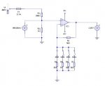
Is it possible to have several voltage dividers (say 5), all connected at the same time. I would have a 1:0 (direct feed), a 5:1, a 20:1 a 100:1 and the 200:1. The PIC would see how many of these read as 255 (eg voltage is higher than supply), and thus get a result to the highest precision possible.

The only problem is you could be feeding 750v straight into the PIC (via the direct link). Is this a problem? I recall hippy posting a circuit where 250v could be fed straight into the PIC via a suitable resistor. Can 750v be fed straight into a PIC (via a suitable resistor)? Will the clamping diodes save me?

Many thanks

Richard
 

Dippy

Moderator
Do you want to ADC the value or simple digital on/off?

A task not be taken lightly in any event and posing a potential safety hazard. Without care, you and your circuit could go bang!
(That's my only pre-emptive doom&gloom message; injury, damage etc. I'll leave you to ponder. Basically: on your own head be it and don't do it anywhere near me).

Obviously you will be considering components with a suitable rating.

Have you considered switched potential dividers, the PICAXE selecting the potential divider to use - a bit like an Autoranging multimeter,

There are many considerations and possible routes to disaster.
Current limiting, source impedances, protection for PICAXE etc.
Maybe you should enlighten the collective as to what the voltage source and application will be.
e.g. are high frequencies or nasty transients involved? Or nice DC with fairly gradual voltage changes. AC or DC? (Sweety).


Many things are possible and if an experienced person gives you sound advice then take it.
If an experienced person is told of the precise application and says don't do it then don't do it.

Finally, what is your level of experience/skill with electrical/electronics?
Is the application likely to affect others (i.e. 3rd parties)?
I would suggest that this is not the sort of thing for a novice without experienced guidance.
If you are a novice then don't jump the gun and assume you know better - I'm thinking of your health.
 
Many thanks Dippy

I am trying to design a rough autoranging multimeter, for when I don't want to use my Fluke.

Do you want to ADC the value or simple digital on/off?

Therefore ADC.

Have you considered switched potential dividers, the PICAXE selecting the potential divider to use - a bit like an Autoranging multimeter,

That was my initial idea. However, what happens when I remove my 5v battery and attach the 700v source? Can it switch in time?

There are many considerations and possible routes to disaster.
Current limiting, source impedances, protection for PICAXE etc.
Maybe you should enlighten the collective as to what the voltage source and application will be.
e.g. are high frequencies or nasty transients involved? Or nice DC with fairly gradual voltage changes. AC or DC? (Sweety).

DC only. Hopefully no high frequencies, but it is a general purpose meter.

Finally, what is your level of experience/skill with electrical/electronics?
Is the application likely to affect others (i.e. 3rd parties)? I would suggest that this is not the sort of thing for a novice without experienced guidance. If you are a novice then don't jump the gun and assume you know better - I'm thinking of your health.


To be used by me only. I qualified and worked as an electrical engineer, and I now work with telephone wiring and exchanges accross the US. I have plenty of experience with HV.

I did think of using a 200:1 divider to work out which divider to use (via relays), but I got stuck working out what happens in the situation where 700v is quickly plugged in. There needs to be some protection to stop the PICAXE getting blown before it can respond by lowering the voltage coming in.

Richard
 

hippy

Ex-Staff (retired)
Using a very large R to feed high V into a PICAXE rests upon making the current so small ( micro-amps ) that it has no adverse effects.

As you note, choosing an R for a lower voltage and then having the voltage go much higher will cause problems, as current increases the diode clamps won't save you, and it could be lethal to health.

It should be possible as auto-ranging meters do that but I have no real idea how, or how to, do that safely ( for PICAXE or people ) with such high voltages. I expect you will have to use some sort of external auto-ranging signal conditioner circuit where the circuit can tolerate such high voltages / currents.

You could have a potential divider which has a fixed high value as Rtop and adjust the Rbot which would ensure low current in all cases but the R's would probably have to be so high ( 15M to give 50uA at 750V ) that this could introduce other problems such as electrical interference; you'd only have 130nA for 2V input.
 

Dippy

Moderator
Well, I've only given this 5 microseconds thought;

How about the big ratio pot-div as the default when there is no power from PICAXE?
The other pot-divs can be switched in parallel - maybe with transistors or maybe use a secondary chip switch thing.
If the pot-divs are switched on the ground side I'm sure a semiconductor solution would be better (certainly faster which may be safer too). If you used FETs then their impedance could be made insignificant compared to pot-div.
I think I'd be tempted to buffer it with an op-amp to protect PICAXE and it may help input impedance issues with PIC ADC too.

I wonder if you can get a pukka multimeter autoranging chip/cicuit from somewhere....
 

fernando_g

Senior Member
There are a couple of things you must do to implement this;

the first is to use a high impedance divider; unfortunately the Picaxe's ADC input likes low impedances. So you most likely will require an opamp buffer.

Schotky diodes connected at the opamp's input and to Vdd and Vss will shunt away any current from the inputs.

The voltage divider must be designed such that, in its rest or unpowered state, it has the maximum attenuation. Then the Picaxe will downrange one step at the time until the desired range is achieved.

Last comment: Make sure that the resistors in the divider chain are capable of withstanding the voltage. Not because of excessive power dissipation ( P = V^2/R) but their actual breakdown voltage.
 
Thanks for all the input everyone.

It sounds like a resistor ladder (switched by relays) is the answer. This would then give an output voltage wich would be fed into an op-amp (for high impedance). Could it use the below schematic to determine if the range selected is too high? The diode is a 5.1v zener. The op-amp would be wired as a buffer. If the PIC reads the output of the op-amp as 5.1v, it means the range selected is too high, and a lower range is needed. Would this idea work?
Code:
                                             .--------.
                                             |        |
      From resistor ladder                   |  |\|   |
                      +       800K           '--|-\   |
                      |       ___               || >--o------------------------ output
                      '------|___|--o-----------|+/
                                    |           |/|
                              zener V
                                    -
                                    |
                                    |
                                   ===
                                   GND
Martin - in answer to why I don't use my fluke, I often leave it at work or in the van. I also need a new PICAXE project to work on :).


Dippy - I agree with your comments on using an op-amp as a buffer, and having the high range as a default. Good thinking!

Thanks for your contibutions

Richard
 
Last edited:

Andrew Cowan

Senior Member
That schematic looks like it would work - just make sure the voltage of the zener is less than the voltage of the PICAXE. I would also look to use a rail to rail op-amp.

A
 

Dippy

Moderator
Oh oh, back to the old zener issues again...:(

With all these resistors kicking about it is CRUCIAL that you be careful with zener protection.
A Zener is NOT an on-off safety valve. It has a performance curve.
Any Zener must NOT affect the signal level over your desired range - though a little bit could be compensated for in code.

If you had a fantasy 'perfect' rail-rail opamp running at 5v , which could stand slightly overlaoded inputs then a 9V zener would afford protection and not upset the signal.

I suppose you could turn this on it's head and have a big safe voltage divider (with a high voltage MOV and fuse on the source side) and your autoranging changes the gain of your buffer op-amp. A bit of care here with design and component choice would probably get rid of the need for a PICAXE-protecting-zener.
Or maybe I've jsut got muddled :(
 
I suppose you could turn this on it's head and have a big safe voltage divider (with a high voltage MOV and fuse on the source side) and your autoranging changes the gain of your buffer op-amp. A bit of care here with design and component choice would probably get rid of the need for a PICAXE-protecting-zener.
Sounds perfect. A fixed 200:1 divider, and then variable gain (from 1 gain to 1000 gain etc). Ideal.

Is the best way to adjust gain to switch between resistors using relays? I know that would work, only question is if there is an easier way. I could also use one of Maxims analogue switching chips, I think.

Or maybe I've jsut got muddled :(
That makes two of us!

Richard
 
Last edited:

Dippy

Moderator
Relays.... clickety click....
With gain switching you can use high resistor values, tiny oppy-ampy currents.
This means than analogue switching using chips or FETs would have an insignificant effect - assuming your desing and component choices are good of course.

For this low power stuff semis are slick, relays are '50s Sci-Fi :)

But, you'd better check all this out. I merely suggested it with absolutely no time spent on thinking the details through.
 

BeanieBots

Moderator
For ultra high precision analogue work, mercury wetted reed relays are often used. However, for basic 10-bit analogue stuff I'd opt for an analogue multiplexer switching resistors on the gain stage of an op-amp. Something like the 4066 qaud bi-lateral switch would do nicely. (watch for switch impedance values)
Keep well away from having zeners anywere near analogue signals if accuracy is of any importance. If the 'knee' is close enough to offer protection, it will have a significant impact on the voltage, if it is far enough away not to effect the signal, it will offer zero protection.
Let the op-amp do the protecting by it's limited output voltage and a series resistor to limit the over-volt current.

800k into a zener. No chance.
What is the leakage current of your zener? How many volts will that lose?

If you really feel the need for zener protection, put a few hundred ohms between the op-amp OP and the feedback node. Then put the zener to ground AFTER the resistor. The op-amp will then compensate for any zener current around the knee point and your signal will suffer much less attentuation.
 
Last edited:
Thanks for the advice, BeanieBots.

The attached circuit diagram seems to work. I would replace the mechanical switches with a 4066.

The only probelm is that it doesn't work with high resistance resistors - if R3 is 1M and the gain resistors are 1M, 100K, 10K and 1K, it does odd multiplication. Is this due to the op-amps limitations?

I would have to correct for the funny gains (2, 11, 101 and 1001) using the software. Alternativly I could use multi-turn trim pots for the gain resistors, and set it so the gain is as it should be.

Thanks again!

Richard
 

Attachments

hippy

Ex-Staff (retired)
Sounds perfect. A fixed 200:1 divider, and then variable gain (from 1 gain to 1000 gain etc). Ideal.
However, for a 2V input you reduce that to 10mV, for a 1000 step ADC that's 10uV per step before applying gain. You could struggle to keep noise out of the circuit at those levels.

In your circuit of Post #16, you want that 399K resistor to be at least two resistors in series, to limit the effects of the resistor failing short-circuit. If that does happen, you get 750V into eveything, and I don't think we need a sweepstake on guessing what happens then.
 
Last edited:

Dippy

Moderator
Well, maybe use both methods; maybe a 2 stage input pot-div and a gain pot div.
Have a play.

Most of this is up to your imagination, planning, component choice, patience, experimenting, testing and probably an oscilloscope.

In principle it is easy, fine tuning will be fun and good experience.

Have a go... after all it can't be too difficult when the world is saturated with 50p multimeters :)
 

BeanieBots

Moderator
Agree with Hippy.
If you attenuate and then apply gain, you are more likely to introduce noise and other errors.

I'd be tempted to use an inverting op-amp arrangement (or even two) and use the feedback resistor to attenuate for high inputs and apply gain for low inputs. To do that though, you would need dual rails for the op-amp which IMHO you should use anyway.

One option for generating the -ve rail would be a diode pump driven from PICAXE PWM output but that method can be noisy and care would need to be excersised not to introduce it into your signal.

Also, don't forget the 4066 type switch can be used in both the attenuation and the gain stage as long as no input voltage exceeds its supply rail. So for example in your circuit, there is no reason why you could not also 'adjust' the value of the feeback resistor (R3) as well as the gain resistors (R4 - R7).
 
BeanieBots - I've lost you. Can you show me a link that describes what you are saying? Dual supply rails is no problem - I'll have lots of different voltages around.

Richard
 

BeanieBots

Moderator
Don't know of a good link off hand but just about any op-amp tutorial site will show the basic building blocks. Dr_Acula has even posted one here.

The basic INVERTING op-amp circuit only has one input resistor.
It feeds a CURRENT (I=V/R) into a virtual earth.
The output voltage is proportional to the current (hence voltage) but it is negative. That can be fed into another inverting stage to produce a positive voltage.
You then have more resistors to 'play' with using the 4066.
The maths is also easier with the inverting op-amp.

R1 = input resistor, R2 = feedback resistor.
Gain = -R2/R1.

Hence, you can simply use decade values for R1.
Pick R1 as say 1M, then if R2=100k you have /10
If R2=10M you have *10.

In practice, you should avoid such high values unless you have a very good (low bias current) op-amp, so maybe go for /10 on the first stage and then a gain of up to 100 on the second stage.
 
Last edited:
Top