Using a pnp transistor as a Switch

picguate

New Member
Dear Friends,

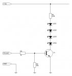
I'm trying to use a 2N3906 (pnp transistor) as a Switch between 5V and 12V, this using the pulse Low or High of my PICAXE to activate or desactivate it.

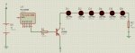
The problem is that my transistor all the time is saturated (active), I tried to make some numbers to calculated the resistors but up to now I dont found a solution.

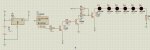
The problem is that I already made the PCB with all de LED installed, for this reason I need to get the 12 V at the transistor collector.

I don´t use relays because my circuit works with 8 Mhz then it could be damaged.

I don't use optoacoplers because is too late to make big changes to my desing.

Please help me, because this is very urgent for my.

Here is the circuit that I'm using.

Thanks in advance,
 

Attachments

inglewoodpete

Senior Member
A PNP transistor works in the opposite way to an NPN.

In order to turn a PNP transistor OFF, the base must be between 0 and 0.5 volts negative from the emitter. In your circuit, that means the base must be between 11.5 and 12v to turn the PNP off.

You have 2 options:
Option 1. Use the PICAXE to drive a small NPN with a resistor between the base and the PICAXE, emitter to 0v and a 4.3k or 4.7k resistor between 12v and the NPN's collector. When the NPN is turned off, its collector will be +12v; when on, close to 0v. Connect the existing 4.3k resistor, currently connected between the base of the PNP and your PICAXE, to the collector of the NPN. Your circuit would now have 3 resistors and 2 transistors.

Option 2. Use a 5v negative rail regulator like a 79L05 on the 0v leg of the PICAXE. This creates a 7v pseudo-ground rail. PICAXE + goes to the +12v rail. The PNP would connect to the PICAXE via the 4.3k resistor as per your existing circuit. You have to take a lot of care in connecting the programming load and other inputs to the PICAXE in this configuration: the 0v rail can easily place -12v across the PICAXE.

Since you have asked this question, I assume that you are relatively new to electronics. I would recommend option 1 in this case.
 

picguate

New Member
Thanks for your answer, the option 1 sounds great.... I'll try it, and let you know the results....

Ones again thank for your time.
 

Grogster

Senior Member
With a NPN transistor, the collector is positive and the emitter is ground.
With a PNP transistor, the collector is ground, and the emitter is positive.

Unless the base is pulled idle-high, the transistor will be on all the time.
This is no good in your case, as you don't want a 12v potential on the PICAXE pin - it won't thank you for that! :D

Change the transistor to an NPN type.

I also like base-loading resistors, as these can prevent many odd things happening.
In the case of the attached image, the 10k base resistor to deck will hold the transistor firmly off, unless there is a high on the PICAXE output pin.
 

Attachments

Last edited:

Dippy

Moderator
Heed Grogster's advice.

There is more to BJT than just applying voltages.
BJTs are current amplifiers.

Do not use your circuit, you will get 12V-ish at your PICAXE pin. Your PICAXE will probbaly be saved by the base resistor/clamp diode combo. But your PNP will never go properly OFF.
Consider the current flows. Read up on transistors.

If you wish to use PNPs for high-sided switches where Vsupply >5PICAXE+V then you have to buffer it. That could be something simple like an NPN.
But for switching LEDs just use Grogster's advice.

One thing to remember; transistors (BJT or MOSFET or whatever) are not all-singing magic relays ;)
 

inglewoodpete

Senior Member
A circuit diagram for the high-side switch, described in Option 1 of my previous post.

picguate mentioned he had already made the PCB. (It's always best to breadboard a circuit first to ensure that it works!), so a low side switch could be difficult to implement. ...and so could adding an NPN level changer.
 

Attachments

Grogster

Senior Member
picguate mentioned he had already made the PCB. (It's always best to breadboard a circuit first to ensure that it works!), so a low side switch could be difficult to implement. ...and so could adding an NPN level changer.
Totally agree - I still use breadboards for testing a concept first, UNLESS it is something you have done before that worked, then there is no need, naturally.

Me thinks he might have to make another PCB...

I suppose he could hack the one he has.
 

Dippy

Moderator
Yup, sounds like it's time to bodgit.... sorry, I mean modify the PCB.
Absolutely breadboard - I couldn't agree more.
....as you get older you become more like a Chess Grandmaster and you can do all this simple stuff in your head.

But people MUST get the idea out of their heads that transistors, especially bipolars are merely voltage-level-triggered-relays. And I'm sure most of us have had that illusion in our early days.
 

MFB

Senior Member
PNP drive using only one resistor

The attached schematic shows a high side drive that uses only one resistor.

When the PICAXE output is low the NPN transistor (Q1) is held fully off, which also turns off the the PNP transistor Q2 and the current though the load.

When the PICAXE output is high the Q1 transistor operates as a constant current drive to the base of Q2. The current is set by the supply voltage of the PICAXE and the q1 emitter resistor value. This current is amplified by Q2 and applied to the load.

Note that the high current gain of Q2 may be quite low (20-30) when calculating the value of the emitter resistor. If the constant current drive is too low Q2 may not saturate and then become hot.
 

Grogster

Senior Member
But people MUST get the idea out of their heads that transistors, especially bipolars are merely voltage-level-triggered-relays. And I'm sure most of us have had that illusion in our early days.
I blew up quite a few transistors when I was learning about them, before a more knowledgeable person helped me to understand that. I too considdered then solid-state relays at the start, which we all know(now!) that they are not! :D
 

picguate

New Member
Solution is here

Dear Friends, I really appreciate to all your help, in special tu "inglewoodpete" and "MFB" that helps me to open my eyes to see some mistakes related with transistor theory, and specially because they understand that I couldn't change my PCB because it was made; mainly because after some days working very hard with a project my brain start to fail, jajaja.

The solution that I found was to make a small PCB that I connected at the output of my current PCB, this PCB has two adicitional transistor to resolve the situation, with this solution I leave with 5 Volt the original transitor that works perfectly with this voltage, and next I installed these new ones transistors connected to the 12 Volt section.

Again thanks to all friend that commented here.

Here is my final circuit.
 

Attachments

Grogster

Senior Member
Interesting circuit, and yes, that will solve your problem - if not slightly over-engineered!!! :D

Next time you are at the shops, get yourself a little breadboard - they are worth the cash, then you can test you idea out BEFORE you make the PCB. ;) :)

I'm glad you got it working the way you want though - well done.
 

Dippy

Moderator
I'm glad it's working.

Comments.
1) Capacitors for regulator?
2) R2 & Q1 ; are they really needed?
3) If there is the slightest possibility you could connect battery wrong way around then insert a diode between 12V and Vi(reg).
4) When doing simple schematics like this, try and draw it so that power lines/signals come from the top and the Grounds/0v come from bottom. Or try and make the signal/bus Powers signals point upwards and the ground/0v point downwards - thats common practice in the big wide world. Sometimes tricky I'll admit ;)
Otherwise, a neat schematic.


And I totally agree about the need for breadboard. Yes, mistakes teach us; but it's easier to fiddle about with breadboard. Well worth a few quid.
 

Grogster

Senior Member
4) When doing simple schematics like this, try and draw it so that power lines/signals come from the top and the Grounds/0v come from bottom. Or try and make the signal/bus Powers signals point upwards and the ground/0v point downwards - thats common practice in the big wide world. Sometimes tricky I'll admit ;)
Otherwise, a neat schematic.
Yeah, I was taught to think of it as water flow: Water will always flow downwards, unless you are on the moon or something, so supply lines on the top, signal or other in/out about the middle if possible, and grounds at the bottom.
 

jeffwang

New Member
If I remove R2 and Q1, and change from +12V to +5V, +5V to +3.3V. what are the value of R3, R4, and R5? ( used MMBT3907 for PNP and MMBT2222 for NPN)

By the way, my max load current is 200mA.
 

jeffwang

New Member
If I remove R2 and Q1, and change from +12V to +5V, +5V to +3.3V. what are the value of R3, R4, and R5? ( used MMBT3907 for PNP and MMBT2222 for NPN)

By the way, my max load current is 200mA.
 

westaust55

Moderator
If you are starting from scratch, why not consider a single NPN transistor as a low side switch.
The indicated MMBT2222 has a Ic rating of 600 mA and thus sufficiently rated - just drive the transistor into saturation to minimise Vce and heating of the transistor (at 200 mA, Vce(sat) = ~0.6 Volts).
Hfe(sat) is not mentioned in the MMBT2222 datasheet I found but typically will be around one-tenth of the Hfe in the linear range for the same current Ic.


All you then need to do is switch the string of LED's around and feed/connect from the supply side and then have the transistor emitter to 0V.
 
Last edited:

westaust55

Moderator
Thinking further,
While the MMBT2222 can handle the 200 mA load current, at that load current my best estimate based on Hfe for 150 mA load as typ = 50mA so assuming the Hfe(sat) will be around 10 - which is very low.
the base transistor current will be around 200 / 10 = 20 mA which is on the high side (ie limit) for a PICAXE IO.
 
Top