Transistor recommendation (quick question)

Hello everyone, little question I will be recieving some led matrix's soon. I have been looking a lot on how to multiplex them(maybe in the future i will get a driver). Any way it is an 8x8 led matrix so 16 pins are needed to multiplex them. I shall use maybe use a double multiplex to cut the io pins needed to 12(I understand the concept but will be very difficult to keep track of the program I create).

Could someone recomend a transistor type? That can both be used for the cathode and anode? And if possible be avaliable from Maplin (I am heading to southampton on saturday and will get a couple to test). Thank you all for reading and again maybe see you in the finished section one day:L =)
Trevor Boultwood


Link to the LED Matrix (from eBay):http://www.ebay.co.uk/itm/320726819510?ssPageName=STRK:MEWNX:IT&_trksid=p3984.m1439.l2649#ht_2742wt_1396
 

g6ejd

Senior Member
As the LED curent is relatively low (i.e. single transistor NPN connected to a common cathode pin to switch on a row, then max current ~ 8 x 20mA = 160mA), then just about any general purpose transistor like the 2N3904 or 2N5551, the latter being a much more rugged device. Depending on what your doing, i.e. bargraph, or alpha-numeric display will determine your wiring and whether you want to drive each and every LED independently, or as batches or rows. But generally, your PICAXE can source a row of 8 LED's from 8 output pins, allowing each to be switched independently under software control, with a common cathode on switch of a single transistor, driven from another 8 pins to multiplex the cathodes, I haven't checked, but the PICAXE could sink the current to one of it's inputs from one LED or more, but probably not all 8 in a row (say 160mA at 5V exceeds the device dissipation). If you are only ever going to have one LED on at once, then no need for a transistor. Do the multplexing fast enough and your eyes will do the smoothing.
 

westaust55

Moderator
You might like to have a look at some details I posted a couple of years ago for an 8x8 LED matrix using RGB LED’s here: http://www.picaxeforum.co.uk/showthread.php?10836

With the RGB LED”s I used two MCP23017 16IO i2c comms based chips as drivers with transistors. For a single colour display you can get away with one MCP23017 chip.

Some details on transistors also provided therein.
 

BeanieBots

Moderator
As you have already been playing with MAX7219s, that would be my recommendation rather than use the PICAXE and transistors to do the multiplexing. I've seen 3-off 7219s used to drive an 8*8 RGB display to great effect.
If however you want to use transistors, then just about any low signal type will do. I'd go for something like BC317 for the NPN and BC177 for the PNP. Basically, whatever they've got at a reasonable price that can drive the current you need. Just remember that you need both PNP and NPN types for anode and cathode drive lines.
 

g6ejd

Senior Member
Well choice of transistor does depend on usage, as the displays are common cathode (or anode depending on type chosen). If all 8LED's are needed to be on, then a BC317 is not adequate, that's why I chose the other types that are well in inside the maximium load. No need for a anode driver IMO becuase the PICAXE can source the required forward current to illuminate the display.
 
OK, Thank you for all your replys, they are much appreciated =) I have decided to use these transistors that are in fact available at maplin, it supports 200ma which is perfect as I only am doing a pure maximun of 160ma (8 LED's) This will control the common annode (supply voltage). I will pick up the remainding 4 from maplin :p to test and if all goes smoothly i will get a couple more of ebay or someplace else.


Ok I one last question when some one says a picaxe can source I understand how that works but how do i set it not to source if that makes sence. (when it is off and not receiving voltage ) would it simply just make the input to an output then conflicting so now power can go through the pin? or should i be on the safe side and not do this? And is it possible to use the same transitor type to act as the cathode? I have made a a few pictures for you to agree with what one i should go for.

Transistor 001.jpg

Thanks to all, and see you soon =)
 
Thanks for the reply, I understand how transistors work i did read the page you sent me and it gave me a better insight. The only part I am confused about is if i need a transistor for all the cathodes. or can i just sink to the picaxe? Thanks again

Trevor B
 

westaust55

Moderator
Each PICAXE IO pin can sink or source up to 20 mA as often quoted.
But you also need to be aware that the PIC chips also have total current limits as detailed in the datasheets.
For some there is a limit of say 95 or 100 mA per port.
For all chips there is also a max total current which for many of the newer chips may be as low as around 95 mA.
So if all 8pins of a port might source current to LEDs at the same time, the the max per pin is 95/8 or about 12 mA.

IMHO it is better to use an interface between the PICAXE and loads to protect the PICAXE against overcurrent and possible variations due to any increase in chip temp which can affect clock sped slightly for example.
 

g6ejd

Senior Member
Agreed, but there's no reason or need to have any two LED's on at the same time, so the device maximum dissipation will not be reached in normal use, possibly under fault conditions, but rare and worth the risk IMO.

It's not yet clear how the display will be used, for example as a alpha-numeric then more than one LED will need to be on, but as a active bar-chart or something then probably not, and a constantly moving LED will suffice.
 

inglewoodpete

Senior Member
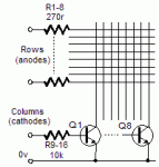
Trevor is a 15 year old enthusiast, already on a fairly steep learning curve. At this point, I would suggest a basic multiplexing circuit like the attached. Once Trevor has mastered to basics of wiring and software, an i2c interface chip and more complex multiplexing can be added.

For the time being, I suggest the following circuit. The 270r anode resistors keep the current through each output pin below 10mA and consequently, the maximum port current under 80mA. Of course, only 1 of the cathode transistors should be turned on at a time, in sequence.
8x8 LED Matrix.gif
 

Paix

Senior Member
it seems that IPete is offering very sage advice Trevor. One other thing, please, oh please, start a Grimoire (notebook) of everything that you make and have proven to work for you. Document it well and index it, because in five years time, you will have forgotten some of the detail and will kick yourself for not writing it down as you went.

it will furnish you with a "How To" that will last you a lifetime and be a source of potted solutions that will save you reinventing the wheel as your knowledge progresses.

Reviewed once a year, you will marvel at your own progress. Be Inspired and sieze the day. :)
 
Top