Think I might make a new board.

GBlair

Member
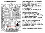
I have came up with a new board layout let me know what you think of it.
I want to use my previous board configuration and just add some other circuits. I got most of the ideas from http://www.thebackshed.com/Windmill/PicLog.asp and this is where I found out about the Picaxe chips. I have incorporated the circuits to measure voltage, current, as well as 2 opto coupler circuits and a Piezo speaker. I was thinking of going ahead and adding a fet and a relay while I was at it. Do you folks think I am going a bit far with this? So far with my previous board I have been able log voltage play music and flash the LED's. I would like to take if a bit further. I think I need to learn a lot more on the programming end and hopefully some Visual basic programming. If any one has any suggestion please let me know. If there is any other software that could interface the PC and the Picaxe other than Visual Basic please fill me in on that as well. If you would like to see what I have in mind it is here http://www.projectgm.com/html/picaxe.html I will put a schematic of the board on later today.
Thanks
Gerald
 

MFB

Senior Member
For plotting and storage take a look at StampPlot Pro. It will accept ten analog channels, plus digital inputs, in binary or ASCII format. StampPlot Pro is well documented and can be downloaded free from www.selmaware.com.
 

manuka

Senior Member
I love your wonderful rendering! Suggest you spill the beans on how you've done this, as other Forum readers will no doubt be keen to know as well.

You seem to have a wide range of electronic interests, but what exactly are you trying to log & display? Given "The BackShed" link is it WIND? Stan. in NZ
 

Mycroft2152

Senior Member
As mentined in a previous thread by Gblair, the renderings are done in EAGLE3D, an addon for the EAGLE Cad program.

EAGLE3D uses the POV-ray rendering program wihich is a ray tracing program. POV-ray os a free rendering program that does some amazing work.

There are a limiitied number of devices in the EAGLE3D library as you can see by the missing devices on the board. Other device images can be created, with the undertanding of 3D modeling. (beyond me)

Myc
 

GBlair

Member
As Mycroft2152 said I used Eagle cad (http://www.cadsoft.de/) for the schematic and Board layout. The ran EAGLE3D ( http://www.matwei.de/doku.php?id=en:eagle3d:eagle3d )after that I used POV-ray ( http://www.povray.org/download/ ) rendering program. There is a tutorial here ( http://www.societyofrobots.com/electronics_Eagle3D_tutorial.shtml ) But I did find another that easier than this one. I will post it when I find it again and will try to do so it soon. If you use the Eagle software go to the download page click on the Libraries link there is a Library for Picaxe. This will help making the schematics easy. There is a learning curve for all of this but once it is set up it is very easy to use. I hope it is okay to put this info on this forum I am not trying to promote or advertise just answering questions and passing on what I have learned. If there is anything I can do to help please let me know. And best of all the software is all free.
Thanks
Gerald
 

GBlair

Member
You seem to have a wide range of electronic interests, but what exactly are you trying to log & display? Given "The BackShed" link is it WIND? Stan. in NZ
manuka I am a Electro / Mechanical Engineering Technician for a Aerospace company by trade. I have many years of mechanical experience but enjoy the electrical part of the job just as much. I am trying to log data from my solar panels and soon want to build some wind mills and would like to log the data from them. I have built a solar tracker for my solar panel and a buddy want to argue that his will work better stationary than mine tracking the sun. Hopefully I can prove him wrong and learn a little in the process. But that is just the beginning. The more I learn about these little gems the more ideas pop into my head. Hope I am not boring or annoying anyone but there is so much more to do and learn and I am just getting started.
Thanks
Gerald
 

manuka

Senior Member
Sure- tracking will win hands down on energy gain- but how reliable will it be even a few months later?

Due to the need for INDUSTRIAL STRENGTH mechanicals ,small scale tracking systems are usually NOT worth it, as they'll initially cost FAR MORE to mount & also need continual maintenance! At their present US$5-10 a Watt you're better off overall just bolting down a few extra panels, slanted perhaps morning/aft! Even seasonal tilting can mean serious mounting & rooftop access concerns.

Here in NZ I've had a range of rooftop rigid mount PVs up in high wind & UV for ~10 years, & aside from bird droppings they've never missed a beat. Anything flimsy would have been destroyed years ago. It's a bit like choosing a sports car (or -ahem-wife), as "good movers " now may mean serious total cost of ownership maintenance issues long term!

Naturally the conclusion may change when setups are large with standardized mounts, especially if paid staff are always on site anyway. Following on from that wife analogy,I guess this is akin to a king who has all sorts of flunkies to attend to his queen when she goes melodramatic.

The graphs below are typical of tracking versus fixed energy output profiles- I don't think these are equal systems. Another issue relates to your local climate, as the region may have morning fog or afternoon cloud that reduces low sun output. Tracking systems will also need provision for seasonal tilt adjustments. NB Low angle winter sun is usually MUCH more valuable that the high summer blasts of course,and some PV systems (even here in NZ @ latitude 41°S) are rigidly mounted near vertically to exploit this. Stan

EXTRA: With an PV or wind system it's of course the "Joules in the bank" that REALLY matter. Hence maybe forget data logging & check an Ah meter based around a bike computer & 08M => www.picaxe.orconhosting.net.nz/bikeamph.jpg & => www.picaxe.orconhosting.net.nz/bikeamph.bas & => www.picaxe.orconhosting.net.nz/bikeamph.gif & => www.picaxe.orconhosting.net.nz/bikepcfb.jpg
 

Attachments

Last edited:

Mycroft2152

Senior Member
As Mycroft2152 said I used Eagle cad (http://www.cadsoft.de/) for the schematic and Board layout. The ran EAGLE3D ( http://www.matwei.de/doku.php?id=en:eagle3d:eagle3d )after that I used POV-ray ( http://www.povray.org/download/ ) rendering program. There is a tutorial here ( http://www.societyofrobots.com/electronics_Eagle3D_tutorial.shtml ) But I did find another that easier than this one. I will post it when I find it again and will try to do so it soon. If you use the Eagle software go to the download page click on the Libraries link there is a Library for Picaxe. This will help making the schematics easy. There is a learning curve for all of this but once it is set up it is very easy to use. I hope it is okay to put this info on this forum I am not trying to promote or advertise just answering questions and passing on what I have learned. If there is anything I can do to help please let me know. And best of all the software is all free.
Thanks
Gerald
Gerald,

I've been speaking from experience. I used EAGLE3D for a while, but decided that I wioud rather spend the time building the boards than just drawing them. :)

Myc
 

Dippy

Moderator
If you normalise those graphs you'll see a healthy difference between tracking and non-tracking . The graphs as they stand are confusing and non-scientific.

I did some quick tests with a small panel recently and it showed a 40% loss when 45 degrees off in a single axis and 60% loss when off by 45 degrees in two axes.

I don't know whether the costs/efforts/possibility of faults of a tracking system is worth it. Or indeed whether the practical installation is worth it. I guess it probably depends on the siting and the application. If you need to extract all the juice you can at any cost and servicing isn't an issue then go wth tracking. Otherwise, I agree with Stan have more panels 'round the corner'.

I was halfway through desiging a little tracking sensor, I don't think I'll bother now.

Oh Stan, when your wife, sorry, car is getting on a bit you just go and get a newer model. One with better suspension, smoother lines, goes faster and has bigger Airbags.
 

moxhamj

New Member
Dippy, those sorts of *cars* tend to cost more! :)

Gblair, you are most certainly on the right track. You have picaxe, eagle and websites mastered. Now it is just up to your imagination. Once you outgrow the 08M, have a look at the 14M, 20M and 18X. There is a picaxe for every application.

Just one thought. Headers, like the 3 pin download header on your board, are non polarised, so potentially you could zap a board if things went in the wrong way. There are many solutions - the stereo download socket, right angle D9 connectors (my favourite), and a technique I have been using where connectors can go either way. So a 5V/0V two way header is replaced with a 3 way one that goes 5V/0V/5V. A three way header eg 0V,Rx,Tx is replaced with a 5 way Tx,Rx,0V,Rx,Tx.

Great board - keep us all posted!
 
Last edited:

Michael 2727

Senior Member
Dippy is looking for a job as an Air Bag Testerer, :)

I'm half way through a new board also,
I thought a 20M Experimenter would be a useful additoin.
 

GBlair

Member
I had a car like that once. Extra large airbags, beautiful bumpers and prettiest blue lights I ever seen. It got to be a little contrary and the maintains cost was way too high. Had to trade it in on one of those economy models but boy wouldn’t I like to take her around the block one more time.

I just got today in the mail 1 each 08M,14M,18X,28X1,40X1. Just though I would get ready. I also received my DS18B20 today as well. Now if I can figure out how to write a program and set up something to read the temperature data I could move on. Stuck for now but searching for something that I can plug and play while reading the manuals and testing. I have downloaded the program StampPlot as suggested earlier but not figured it out either.

Never give up and never surrender. I am on vacation this week but have the dreaded jury duty tomorrow but hope to keep cracking on this in the spare time.
 

moxhamj

New Member
Jury duty. Picaxe. Hmm, what a choice.

This is how we do jury duty in Australia http://www.news.com.au/mercury/story/0,22884,23845830-921,00.html

See if you can sneak in some chips and a soldering iron and a small laptop. Tell them you are taking notes on the computer or something.

Re plug and play, I usually start off with

main:high 1
pause 500
low 1
pause 500
goto main

The program just grows from there. If something doesn't work, the explanation is usually in the manual. And if that fails, just ask here.

I'm off to do some more picaxe. My car has a flat tyre.
 

GBlair

Member
My Luck if I tried that I would end up on trial. I don’t want that.

I think I will try and edit the read temp code in Manual 2 and have it send the data to the terminal program in the Picaxe Programming Editor. That should get me started reading the temperature. Right now I have it reading 0-128 without the sensor hooked up. Just testing to see if it would read anything.

The manual had goto loop before the neg: but it did not work so I removed it. And now get the 0-128

main:
readtemp 1,b1 ‘ read value into b1
if b1 > 127 then neg ‘ test for negative
serout 0,N2400,(#b1) ‘ transmit value to Terminal

neg:
let b1 = b1 - 128 ‘ adjust neg value
serout 0,N2400,("-") ‘ transmit negative symbol
serout 0,N2400,(#b1) ‘ transmit value to Terminal

Pause 1000
goto main
 

manuka

Senior Member
You're on the right track, but just use SERTXD instead of SEROUT. SERTXD sends data back up the programming lead to the editing PC, where F8 will open a nifty terminal screen. Talk about seamless! Of course I could tell you the syntax, but it's all revealed in the manual- seek & ye shall find.

Glad the fast car/wife/solar tracker comparisons are giving a laugh. For those of you ignorant of marital "overheads", it's probably fair to say that in comparison a solar tracker will be very cheap learning indeed!
 

Dippy

Moderator
And, of course, if you leave the Missus on the roof of your house then you can't hear her moaning about your hobbies.
 

GBlair

Member
Did not get selected for the Jury Duty. Good thing!

Well made a little head way today.

I did get the temperature to read using this code
Code:
main: 		‘ make a label called main
readtemp 4,b0 	‘ read channel 1 into variable b0
sertxd (#b0,cr,lf)
pause 500 		‘ short delay
goto main 		‘ jump back to the start
which I copied from the book and changed the pin number. And I just figured out how to make it plot the data with StampPlot. I will keep reading and plugging away at this. You know the more I figure out the more ideas keep popping into mind.
 

Michael 2727

Senior Member
I thought I would make a New Board as well ;)

Looking at Stan's recent Silicon Chip article on the 20M and I
was inspired to have a go at a 20M Experimenter board.

With 8 in-line inputs / outputs, I thought what a great simple chip to
use to teach Binary and other Micro, Computer type operations.
As well as the usual Picaxe stuff of course ;)

So I had a go at 20M Experimenter board.
And now I've just realized I have forgotten to include a DS18B20, bugger !
Any other suggestions, omissions, additions, thoughts welcome.
( By the way it's only drawn up at this stage, not prototyped as yet )

Maybe Rev-Ed has something on the boiler as well.
Off to scrounge back PCB real estate to include a DS18B20 :)
And of course Dippy will want front Air Bags and ESP fitted.
 

Attachments

Last edited:

hippy

Technical Support
Staff member
A couple of points on the schematic ... Always try and keep positive voltages at the top, 0V at the bottom, LED's pointing downwards -

PSU Input, top left
+12V at R8, bottom right
OK1/OK2 far right.
 

manuka

Senior Member
20Ms indeed look A1 for all manner of work -article links => www.picaxe.orconhosting.net.nz/20M.htm

I could be interested in specifying this PCB in fact to go with a 20M 2nd article, although it was going to be aimed at a 5x7 LED matrix. A recent N&V (?) article on "the worlds smallest moving message display" had caught my eye as Picaxable with a 20M & such a matrix. See a further project link on the Vero pix below.

THOUGHT: If you're making significant PCB changes perhaps also make provision for a HopeRF HM-TR 433 MHz module on your PCB, as an agent ensuring the Oz. supply of these is under discussion. They could be as abundant as 555s by Xmas!

Stan
 

Attachments

Last edited:

manuka

Senior Member
Fair comment Dippy. Although I may certainly recommend items (ranging all the way from coin shop bargains to $$$$$$) that I've personally verified as "good value", my enthusiasm has long been impartial & non aligned. I'll even go so far as to endorse the old country's amber fluid in the right circumstances-devoted colonials consider that as impartiality bordering on the heroic.
Stan (1st generation Kiwi)
 
Last edited:

Mycroft2152

Senior Member
20Ms indeed look A1 for all manner of work -article links => www.picaxe.orconhosting.net.nz/20M.htm

I could be interested in specifying this PCB in fact to go with a 20M 2nd article, although it was going to be aimed at a 5x7 LED matrix. A recent N&V (?) article on "the worlds smallest moving message display" had caught my eye as Picaxable with a 20M & such a matrix. See a further project link on the Vero pix below.
Stan
Stan,

Do you think the PICAXE 20M will be fast enough? There hasn't been much success with POV LED displays using a PICAXE.


Myc
 

Michael 2727

Senior Member
Stan the board was designed as a learning board, nothing fancy, that would
be the second version the "Project" board, ;)

I Did manage to squeeze in a DS18B20 socket, behind the IR Detector :)

I don't have a UV light box or etch tank anymore, so I'm not sure when I can
make a board up, leave it with me.

I managed to get hold of some RFM DR3100 433.92 MHz transceiver modules
very cheap, ( 3V, 1.2mW, 2.4 Kbps to 19.2 kbps ) looking for a project for them also.
 

manuka

Senior Member
Yes- moving messages need speed of course, & I've yet to give 20M a 5x7 POV workout- it may indeed be no go. However I'd teasingly pondered sequential letter presentation, much as I've used with the 7 segment LED thermometer. Stan
 
Top