I've been using PICAXE chips for about a year and I haven't run into this problem before.
The circuit:
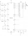
18X Picaxe
Unused inputs tied low thru a resistor
Other inputs going to push buttons and resistor. Other side of resistor goes to common. Other side of push button goes to +5.
Reset is tied high
Serial In tied low.
The program:
At start up a message is displayed on a LCD. When a push button is pressed a different message is displayed.
The program works as expected after initial programming. However, if I turn power off and on again the start up message displays ok but the buttons no longer work.
With a volt meter I verified that the reset pin is high and the serial-in is low. I also checked the inputs while pressing the various push buttons.
Any ideas?
The circuit:
18X Picaxe
Unused inputs tied low thru a resistor
Other inputs going to push buttons and resistor. Other side of resistor goes to common. Other side of push button goes to +5.
Reset is tied high
Serial In tied low.
The program:
At start up a message is displayed on a LCD. When a push button is pressed a different message is displayed.
The program works as expected after initial programming. However, if I turn power off and on again the start up message displays ok but the buttons no longer work.
With a volt meter I verified that the reset pin is high and the serial-in is low. I also checked the inputs while pressing the various push buttons.
Any ideas?