STAMP sized picaxe boards..?

BCJKiwi

Senior Member
@ the Doctor,
Would suggest a USB socket & cable, a USB Plug and extension cable, or hard wired USB cable for a dev board.

That way you can keep the unit on the breadboard or whatever and not have to plug it in and out.

I wouldn't be very happy with a card like that plugged directly into a PC - too much risk of damage.
 

Mycroft2152

Senior Member
BCJKiwi,

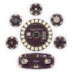
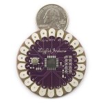
I agree, something similar to the Iduino. that would be the most 'commercial' of the form factors. Either using through the hole or smt PICAXE chips.

Then the next question is 18X or 28X1?

There have been a recent thread about using th FT chip, the rest is an excersise in CAD.

Myc
 

moxhamj

New Member
18X or 28X1? Up until recently I would have said 18X, but looking at the UK prices there doesn't seem much between the price, yet the 28X1 does deliver a lot more. So I think I would say 28X1.

With respect to what goes on the board, the discussion could go on forever. Mycroft's footer says it all!

I've just finished soldering up some 18X boards that have gone through several iterations. Final design has 4 RS232 connections, radio link, 4 analog outputs, 4 analog inputs and 4 relays, with a 20x4 LCD display. It works with a wireless and wired mesh. And a software package in VB.net that allows links to be created easily. It is really hard deciding what to put on a board and what to leave off and whether to put everything on one board or build boards in modules. I guess the application decides that. For me, the application is measuring tanks and stock troughs and turning on pumps so size doesn't matter and all components can be DIP.

But if the application were robotics, then surface mount has lots of advantages.
 
Last edited:

Mycroft2152

Senior Member
An all SMT would be very tiny.

But how many people would have the abiltiy to successfuly solder an all smt kit?

Back to the definition of "commercial". After all, you want to maximize sales.

From my brief survey of the various form factors, presoldered smt dips seems to be the compromise.

For breadboard compatible footprints, there seems to be 24, 28,34 and 40 pin versions. Depending on the I/O's on the microprocessor.

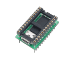
There was one 24 pin hybrid, with an extra 4 pins as solderpads tucked on the end of the Stamp form factor pcb.

Myc
 

Craftybytes

Senior Member
I did not realise that this thread would generate such interest..!!

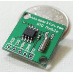
For what it offers in i/o & program memory I'm mainly going for the 28X1 chip as the 'base' micro for my smd PCB project - along with a DS1307 RTC & 24LC256 serial eeprom..

@Myc - "But how many people would have the abiltiy to successfuly solder an all smt kit?"

Well I'm thinking that when I go ahead with this - my smd PCB effort will have all the relevant components already soldered to the board - only some extra pads available around the edges where suitable for soldering leads or connectors to (if required by the user) - thus removes the need for skilled smd soldering..- basically what I propose is a "plug-n-play" type mini processor PCB that just happens to include a RTC & serial eeprom as extras..!!

And for suitable footprints - am going with the 40 pin IC socket type format - as this offers the most i/o pinout flexibility for the type of 'base' functions that the '28X1/RTC/eeprom' combination provide..

Hopefully all this will be useful to the general PICAXE community as a starter..?

Wish me luck with the PCB layout..

crafty.
.
 

moxhamj

New Member
Well, if you are going to pre-solder them for us, that is even more interesting!

Can we put in requests? I'm presuming you will include the 22k and 10k download resistors and a pullup on the reset? A LP2950 5V reg and associated 22uF and 0.1uF caps? Surface mount, of course.

These are components I tend to just mindlessly add before even thinking about what the project needs to do, and it would be great if they were already there!
 
Last edited:

slurp

Senior Member
The stamp style controllers are always more expensive, the PICaxe is cheap and easy - we'd lose some of that with a stamp version.

OK I guess you can put a few bells and whistles with it, and that might be nice, but at that point I'd rather have the single board computer or application PCB.

I guess it's a matter of preference ;)

regards,
Colin
 

Texy

Senior Member
Maybe a bit early to discuss, but are these going to be supplied pre-built or as kits? I would favour the kits as I,m not scared of smt soldering, but also it would give the end customer an option as to which peripheral chips are used. If the DS1307/1337/1338 has the same pin out, then the customer could decide which he uses. Also Craftybytes, could you update your profile so we know where in the world you are? Shipping costs will obviously add to the costs,but if you are in the UK then postage costs will be minimal (for me:D).

Texy
 

Dippy

Moderator
Yeah, but Colin, for some people a 2 or 3 component download circuit is a mountain... let alone a 3 component regulator. Why do BS2x sell so well?

Interesting. You can see the 2+ schools of thought emerging; a StampAXE or a mini SBC....with "I'd like this and that on-board"... and those pennies keep adding up.

I'd do a quick layout of what YOU want and get a ballpark costing asap.

So, you're looking at a 40-ish pin DILx0.6" format?
AXE28X1 + Reg + Enh/Download + EEPROM + DS1338? (Which is advantageous over 1307 deffo)
Good basics. It will all fit easily.

Will it have the edge-clip type pins of a BS2x Stamp DIL? Or leave it with pth holes?

And you will have it assembled factory style?

At a complete guess, loosely based on other things I've had done, I reckon £7-£8 per board for 250 off. (Maybe a touch less, all depends on quantity discounts).

You'll want to make a little profit so you sell them to a distributor for a tenner... if they'll even take them(??). You should check on this first.
They'll want 80% to 100% markup. So retailed at £19 or US$39.

Well, thats still a lot cheaper than a BS2. Go for it, get a pukka costing. Sounds good.

If you make a general purpose SBC you will keep one or two people happy but alienate those doing projects on a tight budget and those who wish to spend 3 weeks saving 10 pence.
As I implied before; My ONLY worry is that if this were a marketable product, why haven't Rev-Ed done it as it is such an obvious value-added product??

Red Herring: One thing I would like to see is a proper Eval board like MilkroElektonika's offerings. But I can't see any PICAXER spending £40 or more. We're working at the 'thrifty' end of the market here.
 

tarzan

Senior Member
A few reasons for not using a surface mounted Picaxe:
Firmware updates
Damage done to picaxe during mishaps
Negate the ability to swap out for X1/X2
 

Dippy

Moderator
True Tarzan. Good points. Obv those points apply to any pcb using sm PICAXEs and the 'damage' issue will apply to any sm component. Ah, the dangers of sm.

But, thems the risks you take eh?
Doesn't seem to worry Parallax too much.
And doesn't seem to worry BS2 buyers much too either.
Is the 28X1 firmware pretty well 100% now? If so, don't worry about the fimware issue.

However, having said that, any failure rate would have to be inluded in the costings. So, an important point in reality.

Will a 28x0.3" DIP and all those other bits fit on 40 x 0.6" pcb? Perhaps with some SMD under the socket?
Or, maybe next month you just bring out the 28X2 version....
 

Dippy

Moderator
Very true, I've used that method on modules. Makes things compact.
Downsides: module has to be removed to change battery, and , assuming mass-ish production, a second soldering process for B side... the cost is starting to mount.

And I think you may have a size problem on 0.6"DIL/DIP sized pcb with a battery holder.
I have no doubts a slightly larger device with all these things is better, I just worry that if you add too much the price starts playing on people's minds.
Some time ago I co-designed a single board device which was a PIC GLCD driver plus SD Driver + RTC (with , btw, battery backup on reverse side). And then I got the manufacturng quotes. It went to the back of the drawer. So be aware of costs and how they can easily grow due to excitement and 'what if I add this'.

Anyway, good luck. It's a good idea, but its time to make up your mind what you are trying to achieve.
 

westaust55

Moderator
presuming that the clock is not required to be maintained in operation when the STAMP-like PICAXE module is removed from the "mother-board" then an alternative is to mount the battery on the motherboard and use one of the 40 pins to bring VBATT onto the STAMP-like module.

If the DS1337 is used as proposed by BCJKiwi, then there is no inbuilt battery backup function in the RTC althought, as BCJKiwi has mentioned in past threads, if the clock supply is kept segregated (diode, etc) then a remote battery could be still be used to the VDD pin from the "mother-board" (again a separate pin required) .
 

westaust55

Moderator
Maybe a bit early to discuss, but are these going to be supplied pre-built or as kits? I would favour the kits as I,m not scared of smt soldering, but also it would give the end customer an option as to which peripheral chips are used. If the DS1307/1337/1338 has the same pin out, then the customer could decide which he uses. Also Craftybytes, could you update your profile so we know where in the world you are? Shipping costs will obviously add to the costs,but if you are in the UK then postage costs will be minimal (for me:D).

Texy
In the 8 pin packages, the DS1307 and the DS1338 are 100% identical. The DS1337 used pin 3 for a second interrupt INTA and foregoes the the Battery backup VBATT input pin.
In terms of capability, the DS1307 and DS1338 are identical other than the DS1338 is 400kHz (i2cfast rated). The DS1337 has no NV RAM but instead has TWO time-of-day alarms.

Both the DS1337 and the DS1338 are also available in a "C" version 16 pin SMD package which includes the necessary crystal oscillator. Both use only the "top 6 pins" relative to pin 1 (ie 1,2,3, 14, 15 & 16). I guess the phicsically longer package is to give room for the internal oscillator.

EDIT:
if the battery for the Battery backed versions wase off board to STAMP-like module (i.e. on the "mother-board") then the VBATT /INTA pin could be brought out on one of the 40 pins and a jumper used on the "motherboard" for conenction to a back-up battery or to provide the second clock interrupt signal.
The "C" version could be an advantage as no need fo a separate crystall socillator so one less component to position and overall real-estate required no greater.
 
Last edited:

hippy

Ex-Staff (retired)

MPep

Senior Member
@Crafty,

Double-sided SMD boards are usually done, in a factory that is, by first dropping down a squirt of a glue-type substance. This has a high re-melting point. Components are then placed where they should be and go through the reflow oven. Then the board is populated on the otherside. Without the glue this time, unless specifically requested. Usually for high ambient temperature environments.
 
Top