I am sorry, I seem to still have a problem with pin numbering.
I am now playing ith the SRF 005. I understand the trgger out on (output) pin 6, but cannot figure out hoe to resd the returning signal.
I am using this code, ripped off the SRF data sheet :-
When I run the simulator, output pin 3 ( physical leg 24 ) flashes as does the TXD (physical 7)
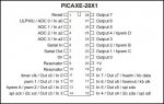
I cant equate the TXD with echo=6 'define input pin above. Should I be using an ADC input or input 6 ( physical 17) By the way, 28x1 chip
thanks, Russ
I am now playing ith the SRF 005. I understand the trgger out on (output) pin 6, but cannot figure out hoe to resd the returning signal.
I am using this code, ripped off the SRF data sheet :-
Code:
symbol trig = 3 ‘ Define output pin for Trigger pulse
symbol echo = 6 ‘ Define input pin for Echo pulse
symbol range = w1 ‘ 16 bit word variable for range
main:
pulsout trig,2 ‘ produce 20uS trigger pulse (must be minimum of 10uS)
pulsin echo,1,range ‘ measures the range in 10uS steps
pause 10 ‘ recharge period after ranging completes
‘ now convert range to cm (divide by 5.8) or inches (divide by 14.8)
‘ as picaxe cannot use 5.8, multiply by 10 then divide by 58 instead
let range = range * 10 / 58 ‘ multiply by 10 then divide by 58
debug range ‘ display range via debug command
goto main ‘ and around foreverI cant equate the TXD with echo=6 'define input pin above. Should I be using an ADC input or input 6 ( physical 17) By the way, 28x1 chip
thanks, Russ
")