I started a Thread on 9 Apr 2013 “EMC Testing” before attempting to get my control circuit based on a 20X2 through the UK EMC tests. People gave me helpful time and advice and I’m reporting back here after completion of the testing. This is the same material as in the main Forum thread:
http://www.picaxeforum.co.uk/showthread.php?25020-EMC-Testing-%96-my-experience
The April 2013 thread gives more background and is
http://www.picaxeforum.co.uk/showthread.php?23667-EMC-Testing
I am keen for people to benefit in particular from the EMC aspects of my experience and it was suggested that I re-post on this Forum.
The controller is for controlling the 12V pump in a solar thermal system. After 4 half-day visits to my test facility, I finally had a pass. There were three areas requiring work:
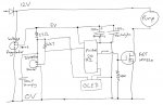
Firstly - The Original Circuit
Here is my original circuit, somewhat simplified (eg no download cable, non-relevant input removed and only one of three DS18B20 sensors shown).
Some notes:
The control circuit PCB is in a plastic box.
The pump has a brushless motor, it does not produce back emf. Following the April Forum discussion I removed its motor capacitor. The lead from the control box to the motor is a 20cm length of simple two-core speaker cable.
About 4m of the same speaker cable powers the system from a 12V switched mode power supply.
There are three DS18B20 temperature sensors, on 2m – 6m or so leads, simple 4 core ‘alarm cable’ with one core not connected to anything (3 core not available). One sensor shares a lead with the OLED for some of the way. One capacitor covered all the sensors (the OLED has its own)
The 27 ohm resistor covered power to all the temperature sensors & OLED and was intended to protect the circuit if a short occurs in a lead or connection.
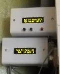
The OLED is the AXE133Y, its lead is 3 – 5m long and its in a plastic box.
The frequency is reduced to 4 MHz which is that used by the ReadTemp command. As I need ReadTemp that seemed to be the lowest frequency possible.
Emissions and pwm
The first tests showed the motor was associated with noisy radiated emissions above the permitted limit.
· The problem only arose when the power to the pump was being reduced using pwmout.
· Using a linear power supply rather than a switched mode power supply actually made it worse
· Adding ferrites on the power line to the pump did not help enough
· Conducted Emissions were not a problem
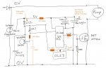
The problem was solved by adding a 1K resistor to the connection from the output pin to the FET. I tried 2.2K as well and 1K was sufficient to reduce noise with only a slight increase in temperature (0.5 deg C) recorded on the FET heat sink, and a slight change in total power consumed. The 2.2K caused a higher temperature rise and a higher power consumption.
See the updated circuit diagram with this and the other changes.
Common Mode (conducted) RF Immunity - Cables to DS18B20 probes and OLED
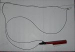
Any cables longer than 3m needed testing, which confirmed there were problems with both the leads to the temperature probes and the OLED. Noise added to the leads with a heavy coil thingy knocked out the signals.
The book recommended to me by this Forum back in April was helpful. It’s by Tim Williams: “EMC for Product Designers”. The Fig 13.16 on p358, for example, suggests that capacitors are needed due to the high impedance at each end of the signal cables.
I did tests with a piezo gas lighter connected to a circuit to produce transient currents – see next post. It showed the vulnerability was reduced by a combination of resistors on the signal and capacitors to ground. The capacitor should be on the cable side, the resistor nearer the pin on the 20X2. The values for these components were eventually derived using trial and error (hence several visits to the EMC test facility). For the temperature probes with more than 3m cables a filter is needed at the PCB end only. The resistor is 330ohms and the capacitor 2.2nF.
For the OLED signal cable a filter is needed at the OLED end only. The resistor is 1K and the capacitor 10nF. The 5V supply also needed a 12 ohm resistor at the OLED end, to prevent loss of voltage I reduced the 27 ohm resistor beside the voltage regulator to 12 ohm.
I tried twisted wire pairs instead of simple alarm cable, but it was marginally worse with twisted pairs.
I added a code signal, the number 199, to the OLED prior to any other signal. If serin in the code controlling the OLED read a byte variable equal to 199 then it went on to read the data to display. So if the signal was corrupted, the display didn’t update rather than displaying random spurious messages.
The system only just passed these tests, I was told that to get better results the only option would be shielded cable and enclosures etc. For the final circuit, the vulnerability was greatest at the high frequency end, eg 30 to 80 MHz.
Susceptibility to Voltage Shocks
In the EMC tests, this is the items ‘Fast Transient Immunity’ and ‘Surges’. The shocks were applied to the 240V supply to the switched mode power supply and to the signal cables (to DS18B20 probes and OLED)
The shocks knocked out the controller and it restarted after the test. This was a pass, but it showed vulnerability and I was strongly advised to address it.
Firstly, I worked on the circuit layout on my PCB, based on the Tim Williams book. I made it into 3 zones: (a) 12V supply, the voltage regulator and pump power control, (b) interface for temperature & OLED leads and (c) the inner protected circuit around the 20X2 chip. Each zone had its solid ground plane on the underside of the PCB and they were connected together at one central point only. All the signals & 12V/5V lines were on the upper plane of the PCB.
I then added a 220ohm resistor in the 5V supply to the 20X2 chip. Tests with the piezo gas lighter showed the vulnerability was resolved without problems in voltage to the chip.
http://www.picaxeforum.co.uk/showthread.php?25020-EMC-Testing-%96-my-experience
The April 2013 thread gives more background and is
http://www.picaxeforum.co.uk/showthread.php?23667-EMC-Testing
I am keen for people to benefit in particular from the EMC aspects of my experience and it was suggested that I re-post on this Forum.
The controller is for controlling the 12V pump in a solar thermal system. After 4 half-day visits to my test facility, I finally had a pass. There were three areas requiring work:
- Use of pwm
- Cables to DS18B20 temperature probes and separate OLED/LCD display
- Vulnerability to electric shocks in supply and signal leads
Firstly - The Original Circuit
Here is my original circuit, somewhat simplified (eg no download cable, non-relevant input removed and only one of three DS18B20 sensors shown).
Some notes:
The control circuit PCB is in a plastic box.
The pump has a brushless motor, it does not produce back emf. Following the April Forum discussion I removed its motor capacitor. The lead from the control box to the motor is a 20cm length of simple two-core speaker cable.
About 4m of the same speaker cable powers the system from a 12V switched mode power supply.
There are three DS18B20 temperature sensors, on 2m – 6m or so leads, simple 4 core ‘alarm cable’ with one core not connected to anything (3 core not available). One sensor shares a lead with the OLED for some of the way. One capacitor covered all the sensors (the OLED has its own)
The 27 ohm resistor covered power to all the temperature sensors & OLED and was intended to protect the circuit if a short occurs in a lead or connection.
The OLED is the AXE133Y, its lead is 3 – 5m long and its in a plastic box.
The frequency is reduced to 4 MHz which is that used by the ReadTemp command. As I need ReadTemp that seemed to be the lowest frequency possible.
Emissions and pwm
The first tests showed the motor was associated with noisy radiated emissions above the permitted limit.
· The problem only arose when the power to the pump was being reduced using pwmout.
· Using a linear power supply rather than a switched mode power supply actually made it worse
· Adding ferrites on the power line to the pump did not help enough
· Conducted Emissions were not a problem
The problem was solved by adding a 1K resistor to the connection from the output pin to the FET. I tried 2.2K as well and 1K was sufficient to reduce noise with only a slight increase in temperature (0.5 deg C) recorded on the FET heat sink, and a slight change in total power consumed. The 2.2K caused a higher temperature rise and a higher power consumption.
See the updated circuit diagram with this and the other changes.
Common Mode (conducted) RF Immunity - Cables to DS18B20 probes and OLED
Any cables longer than 3m needed testing, which confirmed there were problems with both the leads to the temperature probes and the OLED. Noise added to the leads with a heavy coil thingy knocked out the signals.
The book recommended to me by this Forum back in April was helpful. It’s by Tim Williams: “EMC for Product Designers”. The Fig 13.16 on p358, for example, suggests that capacitors are needed due to the high impedance at each end of the signal cables.
I did tests with a piezo gas lighter connected to a circuit to produce transient currents – see next post. It showed the vulnerability was reduced by a combination of resistors on the signal and capacitors to ground. The capacitor should be on the cable side, the resistor nearer the pin on the 20X2. The values for these components were eventually derived using trial and error (hence several visits to the EMC test facility). For the temperature probes with more than 3m cables a filter is needed at the PCB end only. The resistor is 330ohms and the capacitor 2.2nF.
For the OLED signal cable a filter is needed at the OLED end only. The resistor is 1K and the capacitor 10nF. The 5V supply also needed a 12 ohm resistor at the OLED end, to prevent loss of voltage I reduced the 27 ohm resistor beside the voltage regulator to 12 ohm.
I tried twisted wire pairs instead of simple alarm cable, but it was marginally worse with twisted pairs.
I added a code signal, the number 199, to the OLED prior to any other signal. If serin in the code controlling the OLED read a byte variable equal to 199 then it went on to read the data to display. So if the signal was corrupted, the display didn’t update rather than displaying random spurious messages.
The system only just passed these tests, I was told that to get better results the only option would be shielded cable and enclosures etc. For the final circuit, the vulnerability was greatest at the high frequency end, eg 30 to 80 MHz.
Susceptibility to Voltage Shocks
In the EMC tests, this is the items ‘Fast Transient Immunity’ and ‘Surges’. The shocks were applied to the 240V supply to the switched mode power supply and to the signal cables (to DS18B20 probes and OLED)
The shocks knocked out the controller and it restarted after the test. This was a pass, but it showed vulnerability and I was strongly advised to address it.
Firstly, I worked on the circuit layout on my PCB, based on the Tim Williams book. I made it into 3 zones: (a) 12V supply, the voltage regulator and pump power control, (b) interface for temperature & OLED leads and (c) the inner protected circuit around the 20X2 chip. Each zone had its solid ground plane on the underside of the PCB and they were connected together at one central point only. All the signals & 12V/5V lines were on the upper plane of the PCB.
I then added a 220ohm resistor in the 5V supply to the 20X2 chip. Tests with the piezo gas lighter showed the vulnerability was resolved without problems in voltage to the chip.