Snap Circuits Picaxe Programming Setup

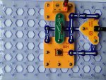
Please find my first project / idea with Snap Circuits® and PICAXE®. It's a very basic circuit but creates the basis for all other projects using this part as you cannot do much if you cannot program the M/C. There was a programming cable offered by the manufacturer but it was a little costly at over £40 when I looked previously but now seems to be unavailable. The circuit just provides power and programming, similar to some of the proto boards I've seen on the forum.

One thing to note is that the Jack Socket uses a 470R for the L and R channels. I have tried programming with and without the resistors and had no trouble but maybe someone could advise if the resistors may potentially cause problems. The Layout used here is not the most efficient use of space but provides the clearest image I can think of to show how to connect the standard PICAXE® programming cable to Snap Circuits®. I have used snap circuits to make many of the projects that use the 08M2 M/C in the book "Programming and Customizing the PICAXE® Microcontroller", 1st edition. I hope someone may find this of interest.

U21 includes the 10K and 22K required for serial in connection.
Below shows how the Jack Socket connection line up to the PICAXE® pins.

L = GND
R = S-In
C = S-Out


SnapPicaxeProgrammer.JPG
 

piclt

Member
Your snap circuit is just an expensive nice and colourful way of connecting things similar to a much cheaper option using a breadboard.
You say you have David Lincoln book Programming and Customising. This book is very well laid out with plenty of examples showing simple layouts and the basic programming circuit, The U21 is a pre programmed version of Picaxe so I assume once you program it with your program you will loose the pre program. Regards your layout picture follow a simple circuit in the book and follows the circuit lines with links on snap circuits. Your socket is an stereo audio socket and needs the 10k and 22k connected as in the book. the 470R is not required for programming it may be for a series resistor for a LED.

Also have you a serial port on your PC or are you using USB port...?? For USB you will need the AXE027 which is USB to 3.5 mm Jack (Audio type adaptor) to program. See the manual in the online editor.
 
Last edited:

Buzby

Senior Member
Your snap circuit is just an expensive nice and colourful way of connecting things ...
I agree. Snap is great for simple electrical circuits, but gets really complicated if you try to do anything with more than a few components.
... needs the 10k and 22k connected ...
OP says the programming resistors are built into the U21 block.
 

piclt

Member
OK, I dont use snap was just looking at the picture posted, but looked up online shops and couldn't find any docs describing it OR pinout details...???
So, looks like have only access to 4 pins for user in/out ....chip pins 3, 4, 5, 6 but labelled on snap as 1, 2, 3, 4.. And then chip pins 2 and 7 are Serialin and SerialOut for programming (with resistors builtin ??)...... Then +ve and Gnd for battery.
Surely that makes it even more complicated for someone learning....Non standard labelling and no diagram of pin connections on the snap board.
 

hippy

Technical Support
Staff member
So, looks like have only access to 4 pins for user in/out ....chip pins 3, 4, 5, 6 but labelled on snap as 1, 2, 3, 4.. And then chip pins 2 and 7 are Serialin and SerialOut for programming (with resistors builtin ??)...... Then +ve and Gnd for battery.
Surely that makes it even more complicated for someone learning....Non standard labelling and no diagram of pin connections on the snap board.
I recall the numbering reflects the port.number convention so, without the download resistors shown ...
Code:
                            Sin          +          GND
                             O           O           O
   Sin   +   GND             |  .--------'           |
  .-------------.            |  |  .----._.----.     |
  | O    O    O |            |  `--| +V     0V |-----'
  |             |            `-----| SI     SO |-----O Sout
4 | O         O | Sout     4 O-----| C.4   C.1 |-----.
  |             |            .-----| C.3   C.2 |--.  |
  | O    O    O |            |     `-----------'  |  |
  `-------------'            |           .--------'  |
   3    2    1               O           O           O
                             3           2           1
.


Your snap circuit is just an expensive nice and colourful way of connecting things similar to a much cheaper option using a breadboard.
That may be true, but it suits Snap Circuit's target audience and fits in with other electronic kits they produce.

I remember some plastic blocks which used to plug into a base board, each of which had a single logic gate with banana sockets, so digital circuits could be easily built. Also much more expensive than breadboard and 74HC's but it was great fun. Best of all it didn't require soldering which is one of the prime selling points when introducing students and novices to electronics.

I got into electronics,, then computing, through the Phillips EE Kit, springs in holes on a baseboard, so I would knock it. I still have fond memories of that green bowl that was a surround for the bulb and the bicycle lamp battery. There are more modern equivalents as well.


Please find my first project / idea with Snap Circuits® and PICAXE®.
Welcome to the forum, and great work.
 
Thank you picit / Buzby / Hippy for the replies. I agree that using Snap Circuits would not be ideal from a development perspective with cost and space implications considered but it is from this, that I became aware of the PICAXE and this forum. So I am thankful that kits like this are available. You may be surprised when I say that I was able to recreate the infrared transmitter and receiver, each on a single base plate, complete with power and programming ports, taken from the book David Linolns' book. Programs for the U21 are still available on the Elenco website, I used a google search "Snap Circuits XP program code download" to find. This will give you the small programs used in the XP manual so, nothing lost. Elenco seem to offer quite good support, even for their obsolete products. I did not state specifically but, the audio jack is used so that you can use the standard AXE027 programming cable, sorry if that was not clear in my post.

The board offers full access to the usual pins on the 08M2, nice drawing, I will add that to my collection of information for the board. As pointed out the labelling offers the port numbers and not the pin numbers. Sorry but I didn't label it, I'm just working with what I have : ). I checked the David Lincoln book and looks like many of the project diagrams list pin and port numbers but I can see that might bother some people. As noted, the target audience for this kit is kids, manual says for ages 10 and up!
 

piclt

Member
Search google "Snap Circuits XP"......thats what was missing earlier....thanks for the link. As I said in earlier posts I could not find any descriptive info for the devices anywhere, not even for the devices being sold in the online shops, just a link to buy it. The manual seems very good and also loads of software.
 
Top