Aries
New Member
Several times I have found myself needing to capture the serial output (sertxd) from a Picaxe project, but without the luxury of being able to have a computer permanently connected to it. Also, the time that the output is actually needed could not be determined in advance, so the output could be very large indeed. For example, one system that controlled the lights worked perfectly for years, but suddenly started to switch everything off at unexpected times. It was impossible to predict when it would do it, and so pretty well impossible to diagnose without some output to show what it was doing and when.
This project – the Serial Data Recorder – takes serial output and stores it in a circular buffer on a pair of Microchip 24FC1025-I/P 1024Kbit (128K byte) serial chips, using hserin to receive the data and hspiout to store it. Hardware serial has the advantage of being able to take data at any standard input rate from 300 to 153,600 baud. hspiout does not interfere with hardware serial. Using a circular buffer means that only the last 256K bytes of data are retained before being overwritten.
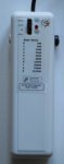
The unit is based around a Picaxe 28X2, operating normally at 64MHz. The input baud rate is selected using the rotary switch at the top right, which is a 10-position rotary encoder connected to pins B4 to B.7.
Edited (26/10/2022 at 19:30): the rotary decoder is connected directly to the Picaxe, not via ADC.
Each notional data block (of 1024 bytes) starts with a header giving sequence number (0-1023), which enables the program to find the first and last blocks that have been recorded.
Connections are:
(left) standard 3.5mm stereo socket for direct connection to the AXE027 download cable;
(top) 4-pin DIN plug on lead, giving SERIN, SEROUT, GND and 5V from the device being monitored.
If the device cannot offer 5V (or does not have the DIN connection, which I use as standard), then there is also a DC socket (right) for an external 5V supply
There is also a CR2032 coin cell to maintain the voltage on the memory chips when the unit is not connected to power.
Operating modes are OFF, RECORD, RESTART and REPLAY, selected with a 2-pole 4-way slider switch (top centre-left).
In REPLAY mode, the unit finds the start and finish of the recorded data and then sends it out through the 3.5mm socket to the AXE027. Where possible, REPLAY mode sends data at the same rate as it was recorded. However, because of the limitations of the chip, 38400 and 115200 baud are both sent at 76800 baud instead.
In other modes, the 3.5mm socket is connected directly to the corresponding connections on the DIN plug. Therefore, the unit then operates as a direct connection between AXE027 and the Picaxe being monitored.
In OFF mode, nothing else happens.
In RECORD mode, serial input from the DIN connector is recorded on the memory chips, starting afresh.
In RESTART mode, serial input is recorded, carrying on from the end of the last recorded block.
In the event of a power failure, RECORD and RESTART both continue from where recording left off.
The box is 125mm x 40mm. My first version, using matrix board, could only hold one memory chip. This later version uses a custom PCB to fit two chips into the space.
Last edited: