Robot design
- Thread starter Andrew Cowan
- Start date
")
“Can you see anything wrong with this?”
I think so.
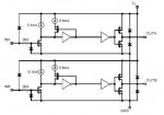
The push-pull circuit in your diagram is supposed to work with a balanced PSU. That is, a PSU that has a ground, a +ve rail and a –ve rail. The output from the emitters is supposed to go through a load to ground, half way between +ve and –ve. The input to the bases is supposed to vary above AND below this ground potential. The load supplies the base current in this sort of emitter follower.
Your load in this circuit is a mofet gate, so almost no current is flowing through the base-emitter of the upper transistor when the input is high. And when the input is low, the base voltage never gets below the output voltage so the bottom transistor can never turn on.
Also, emitter followers always have the drawback of the output never being able to get within around 0.7v of the rails.
Unless you are switching very quickly, there should be no need for a gate driver anyway. The PICAXE can supply about 20mA sink OR source, so the gate will be driven both ways anyhow. If your PWM frequency is too high, and the MOSFET is overheating, just reduce the PWM frequency. I forget the reference just now, but search the forum for ‘prescaler’ or some such. It’s just a simple POKE command.
EDIT:
Oops. My bad. The PWM output can only source current (output high), so you will need to fit a resistor between gate and source to pull the gate back down to zero. I suggest something around the 1k mark.
I think so.
The push-pull circuit in your diagram is supposed to work with a balanced PSU. That is, a PSU that has a ground, a +ve rail and a –ve rail. The output from the emitters is supposed to go through a load to ground, half way between +ve and –ve. The input to the bases is supposed to vary above AND below this ground potential. The load supplies the base current in this sort of emitter follower.
Your load in this circuit is a mofet gate, so almost no current is flowing through the base-emitter of the upper transistor when the input is high. And when the input is low, the base voltage never gets below the output voltage so the bottom transistor can never turn on.
Also, emitter followers always have the drawback of the output never being able to get within around 0.7v of the rails.
Unless you are switching very quickly, there should be no need for a gate driver anyway. The PICAXE can supply about 20mA sink OR source, so the gate will be driven both ways anyhow. If your PWM frequency is too high, and the MOSFET is overheating, just reduce the PWM frequency. I forget the reference just now, but search the forum for ‘prescaler’ or some such. It’s just a simple POKE command.
EDIT:
Oops. My bad. The PWM output can only source current (output high), so you will need to fit a resistor between gate and source to pull the gate back down to zero. I suggest something around the 1k mark.
Last edited:
Andrew Cowan
Senior Member
Sorry - are you talking about the MIC4427, or the 'proof of concept' circuit diagram I made in post 29?
Andrew
Andrew
Post #29, circuit diagram. You asked “Can you see anything wrong with this?”.
You could probably make that circuit work using 3 additional resistors. One from the PICAXE output to ground (say 1k ish), one from gate to +5v (say 470R ish), one from gate to source (say 470R ish). The last two form a potential divider providing the virtual ground required by the push-pull arrangement. It’s not an elegant solution, but it would allow much higher switching speeds.
You could probably make that circuit work using 3 additional resistors. One from the PICAXE output to ground (say 1k ish), one from gate to +5v (say 470R ish), one from gate to source (say 470R ish). The last two form a potential divider providing the virtual ground required by the push-pull arrangement. It’s not an elegant solution, but it would allow much higher switching speeds.
Andrew Cowan
Senior Member
I think I will probably use MIC2247 chip, as it is all of that in one package (twice). Buying one of those chips would be easier than trying to make and troubleshoot a circuit I had designed. I want to run the PWM as fast as possible.
Attached is the circuit diagram for the MIC4427.
Attached is the circuit diagram for the MIC4427.
Attachments
-
 21.2 KB Views: 39
Last edited:
xnederlandx
Member
Wouldn't it be simpler to do it with some high power transistors?
TIP3055 or TIP2955 Seem OK
I'd put two or more in parallel to be on the safe side
You'll need to put another transistor to power the base, so that the picaxe doesn't get overloaded.
TIP3055 or TIP2955 Seem OK
I'd put two or more in parallel to be on the safe side
You'll need to put another transistor to power the base, so that the picaxe doesn't get overloaded.
Last edited:
Andrew Cowan
Senior Member
I don't really know, so I'll wait for sdomeone who does (Dippy!) to help answer this.
200W at 24V = 8.3A. Call it 15 as it will be higher when accelarating etc. Every high wattage motor PWM speed control I have seen on the net uses FETs, not transistors, althoughj I don't know why this it.
Andrew
200W at 24V = 8.3A. Call it 15 as it will be higher when accelarating etc. Every high wattage motor PWM speed control I have seen on the net uses FETs, not transistors, althoughj I don't know why this it.
Andrew
xnederlandx
Member
Hi,
Fet's tend to be able to handle more amps than transistors do, so thats probably why they're used on high-watt PWM modules.
However, since it is harder to drive them with the Picaxe, I don't see why you couldn't consider using some high-power transistors (even in parralel).
However, I don't have any experience in this field, so I'll leave it to someone like Dippy who does have experience.
Some others transistors I looked up:
2N6678 Range
MJ15022 Range - 16A Continuous, 30A Peak.
MJ11011 Range - 30A Continuous, 50A Peak.
Last edited:
Hey, don't blame me for whatever it is ... as I've lost track of this thread and have only a few minutes.
MOSFETs are v. handy. But you DO have to watch out for specs. AND watch out for Driver specs too - there ain't NO MAGIC. This is not Harry Potter.
I'm not going to do your work for you as A) you are able to do it yourself and B) I will charge £50 per hour.
Here's some food for thought:-
1. What voltage do you want for your supply?
2. What is the voltage rating of you driver?
3. The MOSFET driver will be shoving those Vgs up and down faster that a W'sDs. What Vgs values can you expect to see? And will your MOSFET stand it.
4. Why do people (usually on this Forum) PWM the 'top' and 'bottom' transistor* in an H-Bridge config?
5. Can you use a modifed MOSFET driver circuit to power a power BJT?
6. Can you use a BJT/MOSFET hybrid circuit?
7. Why is my Solar Battery charger design only 94% efficient?
8. I have run out of ADC inputs on my PIC, how can I measure a thermistor? (I can't multiplex). I don't need accuracy.
Andrew Cowan
Senior Member
1. What voltage do you want for your supply? 24V for the motors (DS)
2. What is the voltage rating of your driver? 18V, but the gate of the FET only needs 4V. I will use 12V
3. The MOSFET driver will be shoving those Vgs up and down faster that a W'sDs. What Vgs values can you expect to see? And will your MOSFET stand it. Vt=2 to 4V I will use 12V. Vgs max=20V. I will only use it as a low side switch. (IRF1405)
4. Why do people (usually on this Forum) PWM the 'top' and 'bottom' transistor* in an H-Bridge config? So the motor can be reversed. I will reverse it using DPDT relays, so I can use one FET per motor.
5. Can you use a modifed MOSFET driver circuit to power a power BJT? Yes - the datasheet says it can be used to drive any load up to 1.5A
6. Can you use a BJT/MOSFET hybrid circuit? Aren't things getting more complex than the FETs and drivers here?
7. Why is my Solar Battery charger design only 94% efficient? Heat is generated by the resistance of comonents - I will bolt everything to the aluminium chassis.
8. I have run out of ADC inputs on my PIC, how can I measure a thermistor? (I can't multiplex). I don't need accuracy. Use a poterntial divider and a digital input?
FET: http://www.irf.com/product-info/datasheets/data/irf1405.pdf
Driver: http://www.farnell.com/datasheets/112615.pdf
Andrew
Last edited:
Superb!
I must admit I thought you were going to use a 'standard' H-Bridge with transistors top & bottom.
So you'll be usng relays top-side and N-channs bottom side.
I've never understod why people PWM top & bottom.
Sorry, qus 7&8 were a bit rhetorical. For Q8 I can Set output, charge RCR (where Thermistor is part of RCR), set input, time the discharge to logic low. Works well.
Q7: quite right. What a lot of Watts.
Anyway, sounds like you have it sussed. Good stuff.
Andrew Cowan
Senior Member
Clever - charging a cap through a thermistor. Sounds like a fun thing to try.