readadc or readadc10

davidwf

Senior Member
weird happenings

Still plodding on with this.....

something strange is happening when I readADC10 2,w0......
I am "reading" an LDR, when it gets dark the reading falls (as expected) but if I restart the PIC it rises...and rises...but it is still getting dark so it should be falling !
Have also noted this SOMETIMES after any other event in the listing has ocurred

The supply voltage remains steady at 4.9V +/- 0.002 so I don't think it's that !

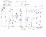
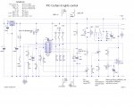
any ideas please, here is the command I am using (lines 165 to 169), full listing attached for reference only as is the cct diagram - with a few alterations from previously

readldr: sertxd(" readldr.... line 165 ",13,10)
readadc10 2,w0
sertxd("LDR = ",#w0,13,10)
pause 2000
return
 

Attachments

Last edited:

BeanieBots

Moderator
C4 is certainly VERY big. 100nF would be more appropriate.
Electrolytics can have some "odd" behaviour, especially if very old.
You don't give any indication of by how much it increases or over what period.
Does it eventually settle down?
 

hippy

Technical Support
Staff member
As ADC1 has a tendancy to sit at 2V5 ( when LDR is ~80K ) the cap will charge up to that at turn-on, with t=RC, you're looking at round 3 seconds for that to happen, and each READADC is going to sample it and in doing so knock it down a bit.

I'm not even sure you need it there but haven't read the full thread recently. Try it without when it's removed before putting in a smaller cap as has been suggested.
 

Dippy

Moderator
Blimey, is this still going on...

Assuming everything is as before that LDR dark resistance is FAAAAAARRRRRRRRT too high. It has to be buffered to get sensible results or use another sensor like that TAOS I post 3 years ago. Microchip don't provide Data Sheets for their amusement, perhaps, maybe for our amusement...?

Don't worry, you'll get there. A three week long thread is nothing here ;)
 

davidwf

Senior Member
Blimey, is this still going on...
Yep, afraid so....

I tried it without the cap and, as before the reading seems to vary (with LDR replaced by a fixed 82K resistor is it rock steady), it varies from about 95 to 105 with a steady light.

Maybe I need to adjust the trigger levels a bit more - you may notice I have added lines 28 & 29 to try and overcome the problem.

value wise I don't have much to play with - even by using readadc10 rather than just readadc....when getting darker the lights on level is 220, the curtains close level is 170, when getting lighter the curtains open level is 100.

I don't think buffering it will help (fixed res is OK)
 
Last edited:

davidwf

Senior Member
C4 is certainly VERY big. 100nF would be more appropriate.
Electrolytics can have some "odd" behaviour, especially if very old.
You don't give any indication of by how much it increases or over what period.
Does it eventually settle down?
capacitor is new, also tried a Tant type (low leakage)

see also post 126....
it increases from about 95 to 105 over about a minute or so, then settles, then starts falling as it should (light level getting dark)....don't understand that at all.

I removed the capacitor completely but it made no difference except that reading varied quicker as I would expect.

As post 126, with a fixed resistor of 82K it remains rock solid, there are no streetlights here (fortunately) and the sensor is pointing down rather than at the sky.

I no understandeeeee :confused:
 

boriz

Senior Member
Once you buffer the LDR, you can arrange for any ADC levels you want. At the risk of repeating myself, “it varies from about 95 to 105 with a steady light.” might just mean the LDR is reacting to the AC ‘flicker’ of your artificial lighting.

“curtains close level is 170”. When using 10 bit ADC, 170 is roughly only 16% of your Vcc (5v AXE supply). That’s about 0.8v!. A reading of 100 is even less. For a decent range and sensitivity, you should have your upper ADC threshold at about 4v (80% Vcc).

So if your upper LDR resistance threshold is 80K as you said previously, in order to have the divider supply 80% of Vcc, the bottom part of the divider should be 80% of the total divider resistance, IE R4=320K.

Although this gives you the proper range and accuracy, the error current drawn by the ADC input is going to be comparatively significant and skew your readings. That’s where the buffer comes in.

If you use the transistor buffer that I indicated in a previous post, with the 320K divider resistor, you should be laughing.

You will probably still have the ‘artificial light’ problem, but that’s another matter.
 

davidwf

Senior Member
boriz,

thanks for that....my humble apologies as I appear to have missed your previous post !
I will try your cct and report back.
There is no artificial light reaching the sensor....in fact there is no artificial light where we live full stop !

Thanks
Dave F
 

davidwf

Senior Member
Boriz

we are guided by rabbits !

....last night I applied your modification to the cct and increased the values to around 600.......this morning I plugged the USB lead in to my laptop to see what was happening and the PIC did a restart.....I never noticed that before, just a co-incidence possibly ?

I don't have the enhanced download cct as I believe it is not required for the USB lead....?
 

hippy

Technical Support
Staff member
USB Reset : That's probably just a coincidence, or it's PC initialisation of the USB device and you've never noticed before. As long as the PICAXE works in its final configuration you will be using in that's enough.

Buffering : The issue isn't voltages or switching point it's, as Dippy says, that the 80K of the LDR is too high for use with ADC. The ADC has a small cap which it charges then measures when it READADC is executed. A large R and small changes will have an effect on the rate of charge and will give slightly varying results.

Four options I can see - Buffering, adding a cap as before but of lower value than it was, putting resistors in parallel with the LDR and the bottom 82K ( I'd suggest 10K to start with ), adjusting the software to handle the varying levels you are seeing to determine a clean switching point.
 

Dippy

Moderator
Trouble is that if you start //ing res then the LDR change has a reduced effect and you may (repeat may) find that the measured light threshold becomes inconsistent.

Have you wondered why Microchip specify an ADC source resistance?

Whereas if you'd used that TAOS device you would have had consistent operation 3 weeks ago :)
 

davidwf

Senior Member
Whereas if you'd used that TAOS device.......
OK, I have it now......before I try it am I correct in assuming that, when read by ADC10, "0" will be fully dark, 1023 will be maximum light and that 512 will be a midway point ?

Is there any (known) correlation between the ADC value and a LUX level ?

Thanks
 

inglewoodpete

Senior Member
Somewhere, if you can identify the LDR model, there will be a data sheet. By their nature, LDRs can have wide tolerances. Some can vary by over 20% in the same light levels, from my experience.
 

BeanieBots

Moderator
As stated by inglewoodpete, the answer is in the DATASHEET.
It will show resistance vs light level.
Your divider stage will determine volts vs light level.
Your power supply will determine volts vs reading.
In a simple divider circuit the "volts" part of the equation can be eliminated from both sides which will give "reading" vs "light level".
 

westaust55

Moderator
LDR's

Have a look at this thread where I did some calcs and tests on LDR's looking at theoretically optimal series resistors for various LDR's.

While some cases use a resistor greater than 10kOhm some tests indicate higher values can work reasonably well.

http://www.picaxeforum.co.uk/showthread.php?t=9265

I found I could not obtain a datasheet specific to any of the LDR's I had access to locally from local suppliers like Dick Smith, JAycar and Altronics.
Jaycars for example just state resistance vales under light and dark conditions but do not indicate exactly what light and dark is.

Attached is an example but it can only be considered an example as varying LDR's have widely ranging resistance ranges. If it can be taken as any guide, 1 lux is extremely low light levels. 100 lux is fairly good. By comparison the average lighting level in a good office is around 300 lux. Normal street lighting may be around 10 lux and freeway lighting brighter still.
 

Attachments

Last edited:

davidwf

Senior Member
Westaust55....thanks for the info but I am going to continue with Dippys' suggstion of using theTSL250R in the hope that it will give a more reliable and consistent input to the PIC.....if nothing else it should stop him moaning at me :D:D:D
 

davidwf

Senior Member
At a loss now.....

Well I'm at a loss now....I installed the TAOS TSL250R as recommended by Dippy and operation seems to be no better than the simple LDR :(
Using this simplified listing,

main:
readadc10 2,w0
pause 30
sertxd(" ldr " ,#w0,13,10)
pause 2000
goto main

I monitored the input to ADC for 30 seconds UNDER A CONSTANT LIGHT LEVEL and obtained these readings

ldr 753
ldr 654
ldr 741
ldr 682
ldr 716
ldr 739
ldr 686
ldr 751
ldr 664
ldr 748
ldr 645
ldr 735
ldr 671
ldr 721
ldr 712
ldr 715

The supply voltage remains at precisely 4.9159V (yes, my meter IS that accurate) but the input to the ADC seems to be varying between 3.4103 and 3.4327 - sorry to be pedantic but I am trying to see what is happening.

These are similar to the reading variations I was getting with the LDR so I am at a loss as to what is going on.
I have replaced the PIC in case that was somehow at fault

cct. attached for reference
 

Attachments

davidwf

Senior Member
Could flourescent lighting be the cause of the variation I am seeing...I have energy saving lights in my workroom and I believe they operate at very high frequency.....surely if affected the ADC would be varying at this frequency ??, but when I turned them off and tried a (DC) torch the reading was rock steady !
.....mmmmm.....:confused:
 

papaof2

Senior Member
Bingo!

The fluorescent bulb switches on and off at the line frequency (50/60 Hz) and the light seen by the ldr or other sensor will vary at that rate. Depending on the point in the cycle that the ldr is read, the absolute illumination level will vary. Your eye doesn't notice this, as it doesn't respond to flash rates greater than 25 Hz - thus making "moving" pictures possible ;-)

You might want to add an RC filter to the output of the ldr to hold the peak level of the room light between cycles of the AC waveform.

John
 

westaust55

Moderator
I do not think it is the fluorescent lights.

While the discharge inside the tube goes on and off with the voltage waveform (and thus off 100 times a second with each zero voltage crossing), the tubes are coated with phosphors (like a CRT screen) which convert the invisible and harmful (to your eyes) emissions into visible light. These phosphors also have persistence so the visible light does no go on and off . If you turn a fluro light off in an otherwise darkened room, you should see the phosphors continue to glow for a while -well I do.

Each off period would be around 5ms duration and the phosphor coating on the tube hold up for at least some of thaat time.

That said, there can be some flicker at the very end of the tubes and in fact a small percentage of people can see this flicker in their peripheral (edge/side) vision which is very irritating.

LDR's themselves take some time to react to light variations. Some typical data is:
Rise Time: (0~63%) 40mS- Decay Time: (100~37%) 10mS
so these sorts of times are equal to or longer than a 100 Hz waveform half cycle so seems unlikely large swings of the LDR circuit would be seen.

so all up, IMHO rule out the fluoro lights - at least in terms of on-off effect.
 
Last edited:

boriz

Senior Member
"...in fact there is no artificial light where we live full stop..."
"...we are guided by rabbits !"

*rolls eyes*
 

hippy

Technical Support
Staff member
Could flourescent lighting be the cause of the variation I am seeing...I have energy saving lights in my workroom and I believe they operate at very high frequency.....surely if affected the ADC would be varying at this frequency ??, but when I turned them off and tried a (DC) torch the reading was rock steady !
.....mmmmm.....:confused:
It could be EMF pick-up, it's already been noted that the ~80K LDR, 82K pull-down puts the ADC into a dodgy area.

Next test is with fluorescent lights on but LDR shielded, and unshielded with torch also shone on it. Then replace the LDR with an 82K R and test again.
 

davidwf

Senior Member
It could be EMF pick-up, it's already been noted that the ~80K LDR, 82K pull-down puts the ADC into a dodgy area.

Next test is with fluorescent lights on but LDR shielded, and unshielded with torch also shone on it. Then replace the LDR with an 82K R and test again.
I am now using Dippys' TAOS TSL250R sensor .... apologies if I didn't make that clear
 

BeanieBots

Moderator
VERY LIKELY to be the fluorescent lights.
I use them to calibrate my tacho which uses an LDR sensor.
Do the tests suggested by Hippy.
 

matt2466

Member
Hi guys!

After a readadc or readadc10 command, the values stored are in binary format correct?

Using the serout, t2400, (b0 or w0) command will it also transmit in binary format or hex?

Thx
 

BeanieBots

Moderator
matt2466, please start a new thread for new questions.
Readadc returns a single byte NUMBER.
Readadc10 returns a word NUMBER.

serout ... (b0) sends a NUMBER.
serout ... (#b0) converts the number to STRING format and then sends it.

eg, if b0=65 then serout ... (b0) will be seen on a monitor as "A"
serout ... (#b0) would send a "6" and a "5".
 
Top