Seems to work ok. http://gluegun.wordpress.com/quick-anemometer/
Quick anemometer
- Thread starter boriz
- Start date
Rather than striping the motor and adding hall effect switches, a full bridge rectifier could be wired across the exciting armature contacts to produce multiple pulses as the motor rotated. A Schmitt trigger would be needed to clean up the pulses before feeding them to a PICAXE counter input.
Jeremy Leach
Senior Member
For info, here's a discussion I kicked off a few years ago about anemometers, with useful replies re using the DC motor as a generator...
http://www.picaxeforum.co.uk/archive/index.php/t-3504.html
http://www.picaxeforum.co.uk/archive/index.php/t-3504.html
Did hot wire anemometers get a mention? These have no moving parts, & work by noting R value changes occurring in response to the cooling of the heated platinum wire by passing breezes.
Forget costly & fragile platinum-Carl & Jerry => http://www.copperwood.com/Carl_and_Jerry-V12N03-A_Hot_Idea.pdf latched onto a cheaper approach back in the 1960s using matched thermistors in a 4 resistor bridge array. Factor in PICAXE number crunching via a simple R difference lookup table (+ perhaps of course data logging), & there you have it. For those of us weaklings fortunate enough to be clear of Gustav's Gulf Coast fury,calibration out the window of a moving car my suffice.
Winds close to the ground are usually buffeting & scudding from every which way, & wind turbines should hence be elevated into laminar ("smooth") flows. A thermistor setup on a tall pole would probably be more rugged than a DIY motor-gene. Brush wear naturally would no longer be an issue!
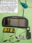
EXTRA: Pulses you say. I've had a lot of fun fooling bike computers into reading Amps & Ah (which are shown as speed and distance). The wind run resource,which is really what you most interested in when small scale wind farming,could be -ah- a breeze.
Forget costly & fragile platinum-Carl & Jerry => http://www.copperwood.com/Carl_and_Jerry-V12N03-A_Hot_Idea.pdf latched onto a cheaper approach back in the 1960s using matched thermistors in a 4 resistor bridge array. Factor in PICAXE number crunching via a simple R difference lookup table (+ perhaps of course data logging), & there you have it. For those of us weaklings fortunate enough to be clear of Gustav's Gulf Coast fury,calibration out the window of a moving car my suffice.
Winds close to the ground are usually buffeting & scudding from every which way, & wind turbines should hence be elevated into laminar ("smooth") flows. A thermistor setup on a tall pole would probably be more rugged than a DIY motor-gene. Brush wear naturally would no longer be an issue!
EXTRA: Pulses you say. I've had a lot of fun fooling bike computers into reading Amps & Ah (which are shown as speed and distance). The wind run resource,which is really what you most interested in when small scale wind farming,could be -ah- a breeze.
Attachments
-
 111.6 KB Views: 48
Last edited:
Manuka, what a great link to get the brain cells working on a Monday morning.
One thing not entirely clear is how many watts of heat need to be generated by the thermister. Clearly there will be not much of a temperature difference if you pass 1mA through a resistor. But just guessing, I wonder if 1/4 of a watt would be enough? You would need enough heat such that heat from the sun is not a factor - and it would probably help if both sensors were in the shade.
There would be no need to run the device continuously - it could wake up once an hour, take a reading then shut down.
I wonder if it could be done with resistors and LM35 temperature sensors? Use a bridge as before, with 4 ?50 ohm resistors. Take two LM35s and strap them to the two resistors at the top of the bridge. One is in the wind, and one is calm. The calm one will heat up more as before. The picaxe could turn the bridge on with a BC337 or similar transistor.
I once built an anemometer out of a stepper motor. You get more volts at slow revs with a stepper, but after 6 months water got inside and it stopped turning. So I like the idea of no moving parts.
Stephen (Steve) Woodward of the University of North Carolina, Chapel Hill, NC has published a number of designs using a self heated transistor instead of a wire to measure airflow, here's the first one I found in google http://www.edn.com/article/CA243221.html
Hmm - good link LizzieB. That has got me thinking about a design idea that would have been hard in 1960 but would be easy with picaxe. Take one resistor and strap a LM35 (or any temperature sensor) to that resistor. Measure the start temperature. Pass current through the resistor till the temperature reaches a set point - eg 50C above ambient. Now turn off the current, and measure the speed at which it cools. Faster wind speed will cool it quicker.
I suspect there will be a log term in there, but a few values in an eeprom lookup table should give a fairly accurate reading. Experiments with a car driving at a known speed can be used for calibration.
I suspect there will be a log term in there, but a few values in an eeprom lookup table should give a fairly accurate reading. Experiments with a car driving at a known speed can be used for calibration.
BeanieBots
Moderator
You've over complicated it Dr.
No need to switch off the heating. Just measure the temp drop caused by cooling effect.
No need to switch off the heating. Just measure the temp drop caused by cooling effect.
Jeremy Leach
Senior Member
I'd guess a resistor's coating might make it a bit unresponsive, plus the temp changes too miniscule to measure easily ??
Jeremy Leach
Senior Member
Actually, Lizzie that's a great link, and his earlier article helps explain a bit more too
http://www.edn.com/archives/1996/031496/06di3.htm
I'm tempted to try this because it looks pretty easy to make, very picaxeable and seems to offer very good results.
There's an even earlier version of his at:
http://electronicdesign.com/Articles/Index.cfm?AD=1&ArticleID=3990
Seems like it's been his pet project to try to perfect, and I think the circuit designs are clever to say the least.
Last edited:
mark.duyvesteyn
Member
asymmetrical wind flow meter
ive been thinking about making an asymmetrical wind flow meter.
The it would look like a standard wind meter,with three "cups" that spin on a vertical axis,but one cup would be slightly larger.
You would get the wind speed by calibrating the average rotational speed,and you would get a spike (caused by the larger cup) which would be calibrated to the direction of the wind.
Any thoughts?
Jeremy Leach
Senior Member
Bit of lateral thinking there. I guess it could work, but the problem I see is measuring the speed. Most methods don't measure the speed during a rotation, but calculate it through revs in set time, or doing a spot check on a voltage etc. Imagine a high windspeed where the time to rotate is a split second, and having to sample loads of speed measurements in this timescale in order to calculate the direction. IMHO I don't think it's very feasible I'm afraid.
It's fascinating all the info out there though. I mean, take a look at this guy's work !! ...
http://www.fonema.se/anemom/anemom.html
It's fascinating all the info out there though. I mean, take a look at this guy's work !! ...
http://www.fonema.se/anemom/anemom.html
It may work Mark.
Surely , for direction, you'd need to measure speed/position continuously as you need to know where your big cup was relative to a reference.
Maybe use a codewheel and sensors.
For a code wheel check out Tom2000's codewheel software. Very clever.
But short answer is that I don't know but I can't see a reason why not.
System speed may be an issue but (within reason) the bigger your device the slower it'll go round.
I think it's time to dabble. Don't forget to balance it all")
Surely , for direction, you'd need to measure speed/position continuously as you need to know where your big cup was relative to a reference.
Maybe use a codewheel and sensors.
For a code wheel check out Tom2000's codewheel software. Very clever.
But short answer is that I don't know but I can't see a reason why not.
System speed may be an issue but (within reason) the bigger your device the slower it'll go round.
I think it's time to dabble. Don't forget to balance it all
BeanieBots
Moderator
Watch a "standard" weather vein with "cups" method for measuring speed for a few minutes.
The vein flaps about and the cups spin up/down quite dramatically very quickly. I don't think it would be possible to use the unballanced cup method because it would not be possible to correlate the difference between instantaneous wind speed change and/or direction.
My thoughts for the mixing pot.
When we go flying, the airfield has a windsock. It visually represents speed and direction. So, how about a lightweight sphere rigidly suspended from a dual axis analogue joystick?
BeanieBots
Moderator
Run the stick straight through the gimbal into a pot of oil and use servo pots.
Dippy- surely you'd prefer "vain"?! Just teasing.
I've been involved with professional wind resource data logging, where $$$$ instruments & several years worth of data are the norm. Aside from max/min, direction & especially seasonal availability - pretty crucial in NZ where our hydro resources are stressed during dry autumns, yet in abundance in early summer- the ultimate interest is of course wind run over time.
This is a measure of energy that could be ultilised, & is especially important when comparisons are made with prospects from nearby windy ridges etc. Hence DIY monitoring should in some way look to measure this "run", & again I mention the appeal of hacked bike computers,which can register this run as a distance. Calibration can be made from a moving car on a quiet road.