PWM help, I'm a bit confused

Ed Straker

Active member
I have been searching through the forum for information on my next learning challenge, using PWM.

I have run into a wall of sorts when it comes to understanding the the Period vs Duty coding relationship.
Since I plan on using this feature to it's full potential, primarily for lighting purposes,
I would really like to get firm grip on what's going on.

I did find some code posted on the forum by Hippy, so this is sort of directed his way, showing a simple fade program.
I tried to decipher what is going on from code only in order to Block Code it out so I might better understand it but was unsuccessful.

So, @hippy:
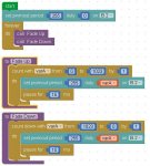
Could you show what this looks like as Block:

Code:
#Picaxe 14M2

Symbol MIN_LEVEL   = 15
Symbol MAX_LEVEL   = 1023
Symbol TIME_MS     = 15000

Symbol MIN_MAX_GAP = MAX_LEVEL - MIN_LEVEL
Symbol STEP_PERIOD = TIME_MS / MIN_MAX_GAP

PwmOut C.0, 255, 0
Do
  For w0 = MIN_LEVEL To MAX_LEVEL Step 1
    PwmDuty C.0, w0
    Pause STEP_PERIOD
  Next
  For w0 = MAX_LEVEL To MIN_LEVEL Step -1
    PwmDuty C.0, w0
    Pause STEP_PERIOD
  Next
Loop

The manuals have created a bit of confusion for me in regard to duty reference.
In code examples, I see duty cycles referenced as 0-255. But in Manual2 it references a range of 0-1023?
I know I am seriously just missing something here.

Since the Period(Freq) is a default 4kHz (which I assume to be more than sufficient for discreet LED work).
It would be the Duty(Fade/brightness) which would be of the most concern?

The monkey in the works came when looked up the PWM Wizard.

4MHz is actually the Clock Speed, ok, understood.

The a period is asked for in kHz, this where it goes off the rails for me as I don't know what Freq would be reqired for a specific
outcome (in my case LED fade and crossfade)

Next is duty cycle (which should be responsible for (brightness in my case) in percent which makes complete sense.

Since there is no pwmduty Block per se, and any duty adjustment would I assume then have to be done via Var"X" commands, this is where I hope the Block conversion of the above code would come in handy for me to begin to fully understand it.

My apologies for the long and hopefully not to confusing post.

Thanks in advance
 
Last edited:

hippy

Technical Support
Staff member
Period determines what the maximum duty will be, how many steps one can have between fully on and fully off. For lighting you will usually want to maximise the number of steps, the duty value.

Setting a period of 255 notionally allows a duty of four times that, actually '(duty*4)+3' but that's more long-winded to say and not usually much different to four times.. Bottom line is a period of 255 allows a duty of 0 to 1023 (full).

That's the highest resolution of lighting steps you can have from off to on -

Period of 255 allows a duty of 0 to 1023
Period of 127 allows a duty of 0 to 511
Period of 63 allows a duty of 0 to 255
etc

You can of course convert a 0% to 100% duty by multiplying the required number to get to that 0 to 1023 or whatever duty value., though the maths can get tricky to do it accurately and you will have reduced yourself to just 101 steps (0-100) if you stick with whole percentages.

The numbers are all consistent regardless of what operating frequency you are operating at so just run at a higher operating speed to reduce any flicker. If there's still too flicker you will need to go up to a higher frequency still, or start reducing the period which will reduce the number of steps in brightness you have.

My recommendation would be to start at default operating frequency, choose 255 as a period, allowing 0 to 1023 as a duty value and see how it goes. You can then control a LED directly from a READADC10 pot ...

Code:
PWM_PIN = ?.?
POT_PIN = ?.?
PwmOut PWM_PIN, 255, 0
Do
  ReadAdc10 POT_PIN, w0
  PwmDuty PWM_PIN, w0
Loop
Basically the 'PwmOut PWM_PIN, 255, 0' sets a 255 period, allows 0-1023 duty, 'ReadAdc10 POT_PIN, w0' reads a 0-1023 value for the pot position, 'PwmDuty PWM_PIN, w0' puts that 0-1023 level out.
 

Ed Straker

Active member
Now I'm really confused, The code snippet I posted was for an auto-fade type program which is what I want to do (eventually to make and auto crossfade) a pot is not going to play a part in anything I plan to do. I don't plan on using readadc for brightness adj. manually.

I know it might seem like I'm being thick-headed but I just don't grasp certain code relationships which is why I asked for a Block version of the original code snippet so I can follow whats really going on and for me at least would be beyond helpful. Or at least I hope so.

If you do a PWM circuit with a 555 lets say, you have 2 variables, clock speed and duty cycle. Simple. Adj via pot/fixed resistor to desired speed and done. But you have no other control over it.

The PWM wizard is asking for internal clk, desired kHz output, and duty cycle.
 

papaof2

Senior Member
Duty cycle = %on vs %off. A pulse could be high for 0.5 of its time and low for 0.5 of its time. Or if could be high for 0.1 of its time and low for 0.9 of its time or the reverse of that - or any set of values that add up to one unit of time.
Internal clock = PICAXE speed.unless I've forgotten - but it's in the manual.
kHz output is asking the frequency of the pulses. Should the output be 1kHz or 30kHz or some fraction of a kHz
? What does the receiving part of the circuit need for its operation?
 

hippy

Technical Support
Staff member
The PWM wizard is asking for internal clk, desired kHz output, and duty cycle.
The first tab of the wizard is primarily for people wanting to create PWM of a certain frequency, the second tab is more suited to what you are doing.

If you select that, System Clock : 4MHz or anything really, Divisor : None, Period: 255, Duty : 0, 511 and then 1023, click "Calculate" and you will see the Generated Duty at the bottom go from 0% to 50% to 100%.

The frequency of the PWM will be 3907 Hz when 4MHz system clock, or higher. Well above 50 Hz so there will be no flickering when driving a LED. Thus the actual frequency is rather irrelevant. What is important is how many steps you want in your light levels and that would normally be 1024 or 256, and that mandates a period of 255 or 63 as previously described.

I am not sure a Blocky version of the original code will help clarify things but here it is -
 

Attachments

Ed Straker

Active member
If I understand you correctly, for LED work, it makes little difference what the Freq value is at 4mhz-div0-duty"x" as long as it is above 50hz ( anything from 1000 - 10000) even doesn't really matter? The period hence doesn't matter much either as long as it is not too low. The higher the better in this case?

On a cursory look at the block code....It absolutely clears things up quite a bit.
If I read that right, changing the "by" value will increase and/or decrease the step/fade speed of said LED. Correct?

I also want to take the time to thank you in advance for the somewhat personal attention. I really appreciate it.
 
Last edited:

hippy

Technical Support
Staff member
If I understand you correctly, for LED work, it makes little difference what the Freq value is at 4mhz-div0-duty"x" as long as it is above 50hz ( anything from 1000 - 10000) even doesn't really matter?
That is correct. Anything from 50 Hz upwards is usually perceived as flicker free by most people but the higher the better, the fewer people will perceive flicker.

The period hence doesn't matter much either as long as it is not too low. The higher the better in this case?
The period will affect the frequency. The higher the period the lower the frequency but it won't usually make the frequency so low that it causes flicker.

The internal PWM mechanism is to count from zero to four times the period, reset to zero and continually repeat. An output signal will be turned on at zero and turned off at one of those values so the number of possible values selected is four times the frequency. The more possible values there are the finer the control of the output, LED Brightness. If the counter went from 0 to 1 you could only have off and fully on, if from 0 to 2 you would only have three possible levels; off, half-on, fully on. When from 0 to 1023 you have the maximum number of possible values the counter allows.

If I read that right, changing the "by" value will increase and/or decrease the step/fade speed of said LED. Correct?
That is correct but as the "by" value is increased the number of steps which will be selected will reduce, the LED in this case may step 0%, 20%, 40%, 60%, 80%, 100% in brightness. The LED won't flicker but those discrete steps will become noticeable.

It is better to retain 0%, 1%, 2% .. 99%, 100% stepping, 0 to 1023 "by 1" in the example, and reduce the pause time between each step.

Plotting duty value or LED brightness over time -
Code:
        ____              ___                _
       |                 |                 _|
       |               __|               _|
   ____|              |                _|
  |                 __|              _|
  |                |               _|
__|__________    __|_________    _|__________
  |    |           |  |           | |
For very short periods of ramping it may not be possible to ramp through the maximum number of steps at a fast enough speed, with a low enough time interval, and the "by" value may have to be increased but the discrete stepping won't be so noticeable at higher speeds.
 

Ed Straker

Active member
Ah, so it's the pause time that is regulating the ramp time up or down.

I gotta make a cheat sheet until I commit this to memory. But just to backtrack for a quick second:

On the PWMOUT command:

'PwmOut PWM_PIN, 255, 0' the "0"(0-1023) is in control of the "brightness" hence for example, If you didn't want the LED(s) to completely turn off in it's ramp cycle, you set a min "X" value and alternately a max "X" value?

Since I'm on the subject, the pwmout signal can be sent to a transistor base pin to control larger quantities of LEDs, but I assume then it has to be a logic level MOSFET and BJT's are out?
 
Last edited:

hippy

Technical Support
Staff member
Ah, so it's the pause time that is regulating the ramp time up or down.
That's right. If you want to fade a LED from 0 to 1023 over one second it needs '1/1023 of a second' per step, about 1 millisecond per step.

Both amount of step and time between steps will control up and down time. It's best to reduce time between steps rather than increase step amount to retain maximum number of steps for a smoother fading effect.

'PwmOut PWM_PIN, 255, 0' the "0"(0-1023) is in control of the "brightness"
That's also right though PWMDUTY, which doesn't need to respecify the period and doesn't restart a PWM cycle is recommended. Blockly doesn't have that as a specific command but that's what the Basic example uses.

If you didn't want the LED(s) to completely turn off in it's ramp cycle, you set a min "X" value and alternately a max "X" value?
Again that's right. 0 to 1023 will go from off to fully on. 102 to 1023 will go from about 10% to fully on. 102 to 921 will go from about 10% to 90%.


Now the real world reality. You will sometimes want to fade two or more channels, often three for an RGB lamp, to change from one colour to the next, may want one to go from 0 to 1000 while another goes from 200 to 800 over the same time.

There's no single stepping rate and stepping amount which will suit both and you can't have fractional step amounts. The solution is to pick a stepping rate and then calculate what would be a fractional rate but as an integer, for example 1023.9 can be represented as 10 times larger as 10239 and you can step that in single units which represent 0.1 of the 1023. You can step that virtual ramp of 0-10239 and then convert that to the 0-1023 the PWMOUT actually requires.

One thing to note is that the PWMOUT, PWMDUTY, period and duty range, how many steps we have, have all been decided, stay fixed from now on. When it comes to varying brightness and how quickly it's only how often we update the value and by how much we step by which matters.
 

Ed Straker

Active member
So if I understand that right in order to power a logic level MOSFET via a pwm pin for multiple LED's, I should be on the very low end of the scale in order to simulate the low Voltage rise required to slowly saturate the FET reproducing the same result.
 

hippy

Technical Support
Staff member
So if I understand that right in order to power a logic level MOSFET via a pwm pin for multiple LED's, I should be on the very low end of the scale in order to simulate the low Voltage rise required to slowly saturate the FET reproducing the same result.
Not following you there, what you mean about being "on the very low end of the scale".

AIUI you want the PICAXE raising and lowering the signal to the gate of the FET as quickly as possible, it's how long the signal is on for which determines brightness.
 

Ed Straker

Active member
Well generally when this is done, my method was to use a NPN BJT (current controlled) Since the PICaxe is a voltage control device, to use more than just 1-2 LED's, say like 10-12, you will need to output the PWM signal to a Logic Level MOSFET in order to power the LED's.

So feeding the FET a 0-30% duty cycle lets say to pwmout, would that not be simulating a low voltage ramp on the Gate giving me the same result as if it were just a single LED connected direct to the PICaxe?

Some cursory examination of the MOSFET's that seem to be common among Arduino users, the LL nMOSFET's prefered are the ones that have a very low gate threshold at around 1.3-1.5v so this tells me the the PWMOUT can be feed right to the gate with more or less the same result?
 
Last edited:

lbenson

Senior Member
It is true that you can directly feed the output of a picaxe pin to the gate of a logic level n-ch MOSFET, e.g. IRL520, IRL540, IRLZ44, etc. I have successfully done this many times. To protect the pin, you may want to pass the signal through a 1K resistor. To prevent glitches, you may also want to pull down the MOSFET gate; 22K is usually available to picaxe users, but anything between, say, 10K and 100K is suitable.
 

hippy

Technical Support
Staff member
I think the pragmatic answer will be "yes, it's the same" as it will achieve the same outcome.
 

Ed Straker

Active member
OK, looks like I've got a LOT of experimenting to do.

I would like the extend a sincere thank you to Hippy for taking the time to help me out as well as everyone else who contributed to help whip a little knowledge on me. Again a profuse thanks to all.
 
Top