Prog. Editor can't count?

FB01

New Member
Editor/Simulator can't count?

Editor/Simulator can't count? :D

Since I'm new here I took the time to put some info in my profile. Have a look to have a bit of an idea who your talking to ;)
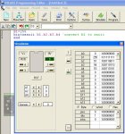
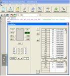
Here is the problem. I've tried various methods of shifting out data but, whatever I do, when I reach count %00000011 it always comes out as %00000101. Here is the code I'm using.

Code:
init:		OUTPUT 0,2,4
      	        INPUT 1,3
      	
    		'Assign labels to in- and outputs 
    		Symbol DAT = 0
    		Symbol CLCK = PIN2
    		Symbol EN = PIN4
    		Symbol PSSIN = PIN1
    		Symbol SRSIN = PIN3
    		
    		'Assign names to registers
		Symbol SHFTREG = b0 
		Symbol STEPS = b1
		Symbol DATREG1 = b2
		Symbol DATREG2 = b3
		
		'Set here start value for data to be send
		DATREG1 = $00
		
countout:	'Shift data out
		let SHFTREG = DATREG1
		STEPS = $FF
		
		Do
  			OUTPIN0 = bit0
			pulsout 2,100
  			w0 = w0/2
		Loop Until STEPS = 0
		
		pulsout 4,100
		
		'Enable interrupt
		SETINT %0010,%0010 		
		goto countout
	
interrupt:	'First wait for button to be released
		IF PSSIN = 1 THEN interrupt	
		let DATREG1 = DATREG1 + 1
		return
The interrupt routine is for upping the counter. The counter can be preset to a start value just before countout: starts. Here you can already set it to 03, so you instantly can see what I mean.

What is happening here :confused:
I am using the editor version 5.2.7


Fred
 
Last edited:

westaust55

Moderator
Welcome to the PICAXE forum.

I am not sure that I fully understand your problem

I tried to simulate in the PE V5.2.7 and it seems to shift through okay.

I tired setting the line just before the cxountout: lable to
DATREG1 = $03

and it still seems to work as expected.


You are using the interrupt to increment the counter.
Is it your intent only to estabilish the interrupt routine for a single pass after each cycle of the countout: loop?

If not then you need to add the line
SETINT %0010,%0010
just prior to the RETURN command so the interrupt remains active.

Maybe a little more explanation of you problem may help members here understand better.
 

hippy

Ex-Staff (retired)
Welcome to the PICAXE Forum.

I'm not sure what 'count' you refer to; if DATREG1, then how is the interrupt triggered ? What controls Input Pin 1 ?
 

FB01

New Member
The program needs to count two different pulse inputs. At this moment, for testing interrupt and shifting data, only one of them is implemented. That I put the SETINT at the end of countout:, just after the DO UNTIL loop, is because I want the shift routine to update the LCD ones (eventually this have to be attached) before the next interrupt can take place.

In a drawing what needs to take place (eventually) is:

_________________________________________________________
PULSE 1 in ------|---------------------|-------|-----------------|
-----------------|--counter with 08M--|..........|----2x8 LDC-----|
PULSE 2 in ------|__________________|-------|_______________|

I hope this answers the question.

Fred
 
Last edited:

FB01

New Member
Welcome to the PICAXE Forum.

I'm not sure what 'count' you refer to; if DATREG1, then how is the interrupt triggered ? What controls Input Pin 1 ?
In the setint, at this moment, I only use one of the two inputs. This is now and only for testing. So PSSIN is used and SRSIN does nothing at the moment. The counter counts, when completed, "passes" (PSSIN) and "rejects" (SRSIN).

You can ignore the 'Assign names to registers part since this was used before I changed the routine. I left it there in case I had to revert to it.
 

hippy

Ex-Staff (retired)
The code seems to be doing exactly as it is coded to do when simulated. It increments DATAREG1 on every interrupt ( when interrupt enabled ) and the 'countout' loop outputs what would be expected.
 

FB01

New Member
The code seems to be doing exactly as it is coded to do when simulated. It increments DATAREG1 on every interrupt ( when interrupt enabled ) and the 'countout' loop outputs what would be expected.
I filmed my desktop and have put the AVI file temporarily online. Have a look how it preforms here :D
In this example it has to shift out $33 but $55 comes out.

http://home.kabelfoon.nl/~fbmac/countersimulation.avi
 
Last edited:

westaust55

Moderator
Ah see what is happening when I look more closely.

if the last digit is for example $x3

then the bits show correctly as %xxxxxx11

but when divided by 2 (w0 / 2 )

the lower two bits show as %xxxxxx10
instead of %xxxxxx01


and

if the last digit is for example $x7

then the bits show correctly as %xxxxx111

but when divided by 2 (w0 / 2 )

the lower three bits show as %xxxxx100
instead of %xxxxx011

Seems like one for Rev Ed programmers to look into.
 
Last edited:

FB01

New Member
Ah see what is happening when I look more closely.

if the last digit is for example $x3

then the bits show as %xxxxxx11

but when divided by 2 (w0 / 2 )

the lower two bits show correctly as %xxxxxx10
instead of %xxxxxx01


and

if the last digit is for example $x7

then the bits show correctly as %xxxxx111

but when divided by 2 (w0 / 2 )

the lower three bits show as %xxxxx100
instead of %xxxxx011

Seems like one for Rev Ed programmers to look into.
So, you see, it's true, at least here on my system. But what is the cause of the phenomenon? Since no one seems to have it on his or her system there is noone to debug it step by step and see where exactly it goes wrong and I have no clue how to do that.

Fred
 

hippy

Ex-Staff (retired)
@ westaust55 : Thanks for that.

#Picaxe 08M
w0 = $FFFF
Do
w0 = w0 / 2
Loop

@ FB01 : Our apologies but this does look like a bug within the simulator which we will investigate. The code should run as expected on a physical PICAXE.

As a workround until the issue is fixed you can replace your "w0 = w0 / 2" with ...

bit0 = bit1 : bit1 = bit2 : bit2 = bit3 : bit3 = bit4
bit4 = bit5 : bit5 = bit6 : bit6 = bit7 : bit7 = bit8
bit8 = bit9 : bit9 = bit10 : bit10 = bit11 : bit11 = bit12
bit12 = bit13 : bit13 = bit14 : bit14 = bit15 : bit15 = 0

I'm afraid I cannot find a shorter workround which works at present.
 

FB01

New Member
@ FB01 : Our apologies but this does look like a bug within the simulator which we will investigate. The code should run as expected on a physical PICAXE.
...
Thanks. Keep me posted. As for the working around the bug. As long as it works 'in the flesh' it's fine!

Thanks again everyone.

Fred
 

boriz

Senior Member
Maybe you can shift the other way. IE:
Code:
Do
 	OUTPIN0 = bit15
	pulsout 2,100
  	w0 = w0*2
Loop Until STEPS = 0
 

FB01

New Member
Well, I tried something else that came up in an other discussion. I had to try it despite the known problem. At least it showed how BINtoASCII works but look at the register values in the attached images...
 

Attachments

Last edited:

hippy

Ex-Staff (retired)
BINTOASCII relies upon division so, with division temporarily broken, all which relies on it will not simulate correctly.
 
Top