Problem measurin RPM of an electric motor

I am trying to measure RPM on an electric motor. I attached a reflective disk (half of the disc is painted flat black see photo on attachments) and use a Fairchild QRB1134 emitter/sensor infrared device. The part of the program is below. The problem is that when the RPM exceeds 15000 the value I get is 0. It seems to be fine at lower RPM values. I don't know if the sensor is too slow or the problem is in the code. I would appresiate any advice including suggestions for different sensing devices.
Code:
...................................
...................
Read_tork=Read_tork-Zero_tork
Sumr=Sumr+Read_tork
pause 100
Next L
L=0
Read_tork=Sumr/4				'Calculate Torque average and store in Read_tork
Sumr=0
			setfreq m32
			Pause 1000
count C.4,16000, W2			'Count revolutions during 2 seconds
w2=w2*30				'Calculate RPM
			setfreq m8
pause 200					
Readadc10 B.0,Read_amp 		              'Read Amp draw
Read_amp=Read_amp*50/1381	              'Convert to amps
Readadc10 B.0,Read_volt		              'Read volts in
Read_volt=Read_volt*5/1023	             		 'Convert to Volts	
Readtemp12 B.2,Read_temp     	              		'Read temperature
Convert:                                    
Read_temp=Read_temp+880/16*9/5-67
Power_out=RPM/100*Read_tork
.............................................
 

Attachments

SAborn

Senior Member
Do you have a cro that you can place on the output from the sensor and see what the wave is like at 15000+ rpm.

Do you have any filtering in the input circuit between the sensor and picaxe, as at high rpm this may just give a linear output and no pulse.
 

Dippy

Moderator
I agree. And post your schematic as the response time will be affected by your circuit design and component choice.
I assume you'vre read the data sheet with respect to response times and the conditions ?
Get the hardware right and then move onto the code.
Out of interest, what happens if you try Pulsin?
 

MFB

Senior Member
The most likely reason for missing pulses at high rpm is too high a value of pull-up resistor on the collector of the photo transistor. A combination of collector and wiring capacitance can act as a low-pass RC filter that cuts-off short pulses. Try using the maximum drive current for the IR emitter diode and the lowest value of pull-up that the photo transistor can still pull to near ground (this should be in the order of 1K).
 

Dippy

Moderator
Ah, you see the problem Marmitas?

You've now got replies on 2 threads as predicted. You're going to get confused.


To others; best to do replies on the thread "Problem measurin RPM of an electric motor".
 

hippy

Ex-Staff (retired)
It's also worth trimming the entire code back to just the COUNT and a DEBUG or SERTXD, check exactly what you are reading as a raw value into W2.
 

Armp

Senior Member
The Ouija Board doesn't like these cold mornings, so I'll have to wait for the full code and schematic....
 

Goeytex

Senior Member
At 15,000 RPM the Frequency is 250 CPS. The sensor will "see" black for 2ms and reflective for 2 ms. This is by no means
a fast signal and even with the sensor's relatively slow rise and fall time of 8us should be no problem.

With a 5v supply, I would suggest using a 1k pullup on the collector to achieve a 5 ma drive signal.
I would use a 470 ohm resistor in the LED circuit to provide about 10 ma current to the LED.

Since we have no schematic to look at , make sure the Transistor is configured as open collector.
See the circuit below.
 

Attachments

Last edited:

Armp

Senior Member
With a 5v supply, I would suggest using a 1k pullup on the collector to achieve a 5 ma drive signal.
I would use a 470 ohm resistor in the LED circuit to provide about 10 ma current to the LED.
According to the spec in post #1 10mA LED current only guarantees about 0.25mA of collector current. So you need about 20K collector load. And it gets worse if your target is not 0.15" from the sensor...
 

Goeytex

Senior Member
The Max LED current ( before failure/damage) is 20 ma. 10 ma is nominal. Don't let the word "guarantee" get in the way.
I have used these before. With 10 - 15ma of LED current, and a good reflective surface and the sensor close to the target,
collector current can easily each 10 - 15ma. In any case I would not exceed 10K in the collector to allow a minimum 500ua drive.

Another option is to put a 1K resistor in series with a 20k pot and test using a scope to find an ideal value.

If it were me, I would probably opt for a photo interrupter instead of a reflective type sensor.
 
Last edited:

Armp

Senior Member
The Max LED current ( before failure/damage) is 20 ma. 10 ma is nominal. Don't let the word "guarantee" get in the way.
I have used these before. With 10 - 15ma of LED current, and a good reflective surface and the sensor close to the target,
collector current can easily each 10 - 15ma.
I think I must be looking at a different spec? Can you point me to the one you're using.

I'm not advocating 'worse case' design for home use, but we do need to be realistic in our assumptions especially when advising other members. At least that's my philosophy...
 

Attachments

Goeytex

Senior Member
Sorry, I got the emitter and sensor reversed. Therefore, for testing on this particular part #, I would drive the emitter (LED) at 30 - 40ma (120 ohm resistor) and use either a 4k7 or a 10K pullup.

With these devices, it is easy to know is the pullup value is is too low as the signal will not fall
all the way to zero.
 
Here is the complete schematic and all the code. At the moment the only sensors I am using are for RPM and the strain gages to measure torque.
Sorry, I got the emitter and sensor reversed. Therefore, for testing on this particular part #, I would drive the emitter (LED) at 30 - 40ma (120 ohm resistor) and use either a 4k7 or a 10K pullup.
I used a 10K pullup and calculated the current limiting resistor R=(5-1.7)/.04=82.5 Ohms.
Code:
' RC Car motor DYNAMOMETER
#picaxe 20X2
  Symbol Disp= C.7
  Symbol Read_temp= W0 	'b0 b1
  Symbol Read_tork= W1 	'b2 b3
  Symbol RPM= W2       	'b4 b5
  Symbol Power_out= W3 	'b6 b7
  Symbol Read_amp= W4  	'b8 b9
  Symbol Read_volt= W5 	'b10 b11
  Symbol Power_in= W6  	'b12 b13
  Symbol Effic= W7     	'b14 b15
  Symbol Zero_tork= W8 	'b16,b17
  Symbol Cal_ADC= W9   	'b18 b19
  Symbol Sumr = W10    	'b20 b21
  Symbol Addr = W11	'b22 b23
  Symbol Volt_Supp = W12'b24 b25
  Symbol N = b42
  Symbol M =b43
  Symbol L =b44
  '****************************************************
  Symbol LED = C.2
  '****************************************************
Symbol COM = 44     'comma
Symbol RET = 13     'carriage return
Symbol LIN = 10     'line feed
Symbol G = 71
M=0
L=0
  '**************************************************
  DirsC = %00100111
  DirsB = %10100000
  ADCSetup = %0000000010100110 ' ADC1,2,5,7
  HSerSetup B9600_8,%00
  hi2csetup i2cmaster, %10100000, i2cfast_8, i2cword
 
  High C.1
  Addr=0
  Sumr=0
   
HSerOut 0, ("?G420")	' configure LCD as 4 X 20
  Pause 500
HSerOut 0, ("?S0")	'Blank Screen
  Pause 500  
HSerOut 0, ("?f")		'clear screen
  Pause 500
HSerOut 0, ("?c0")	' no cursor on LCD
  Pause 500
HSerOut 0, ("?<")  	'exit big number mode
  Pause 500
HSerOut 0, ("?B50")	' Set backlight
  
Pause 500
     Checkbat:
Readadc10 C.3,Volt_Supp 		'Get voltage from supply battery
If Volt_Supp=<614 then goto Buzz	'Sound alarm if battery voltage is less than 6V 

if pinC.7 = 0 then INIT	'Initiate data transfer to PC
HSerOut 0, ("?y0?x00")	'Position cursor at beginning of row 1
  Pause 50
HSerOut 0, ("     HELLO PETE","?n")
  Pause 50
HSerOut 0, ("  PRESS THE BUTTON","?n")
  Pause 50
HSerOut 0, ("  AND HOLD FOR THE","?n")
  Pause 50
HSerOut 0, ("     RED LIGHT")
 
     		Looper:
button C.6,1,255,100,M,0,Looper
'  ***************************
  Pause 1000
High LED			'LED On
High C.1			'Write protect memory
	
  
Calibadc10 Cal_ADC
Readadc10 B.3,Zero_tork
Zero_tork=Zero_tork/2
HSerOut 0, ("?f","?y0?x00")    'clear screen
HSerOut 0, ("  CALIBRATION TEST","?n")
HSerOut 0,("CalVal ",#W9,"?n")
HSerOut 0,("ZeroVal ",#Zero_tork)
Pause 2000
HSerOut 0, ("?f","?y0?x00")    'clear screen
HSerOut 0, ("   WHEN THE LIGHT","?n")
HSerOut 0, ("       IS OFF","?n")
HSerOut 0, ("   START THE MOTOR ","?n")
HSerOut 0, ("AND PRESS THE BUTTON")
Pause 2000
low C.2			'LED Off
Looper5:
button C.6,1,255,100,M,0,Looper5

'***************************************************************************
		Main:
'  ***************************
N=0
HSerOut 0, ("?f","?y0?x00")		
For L=1 to 4				'Read the torque value 8 times
readadc10 b.3,Read_tork
if Read_tork>Zero_tork then Looper4 
Read_tork=Zero_tork
	Looper4:
Read_tork=Read_tork-Zero_tork
Sumr=Sumr+Read_tork
pause 100
Next L
L=0
Read_tork=Sumr/4			'Calculate Torque average and store in Tork_read
Sumr=0
			setfreq m32
			Pause 1000
count C.4,16000, W2			'Count revolutions during 2 seconds
w2=w2*30			'Calculate RPM
			setfreq m8
pause 200					
'Readadc10 B.0,Read_amp 		'Read Amp draw
'Read_amp=Read_amp*50/1381		'Convert to amps
'Readadc10 B.0,Read_volt		'Read volts in
'Read_volt=Read_volt*5/1023		'Convert to Volts	
'Readtemp12 B.2,Read_temp     		'Read temperature
 ' Convert:                                    
'Read_temp=Read_temp+880/16*9/5-67
Power_out=RPM/100*Read_tork		'Calculate power output                                    
PAUSE 100
HSerOut 0, ("TORK=",#Read_tork,"?x10","RPM=",#W2,"?n")
HSerOut 0, ("?x10","Power=",#Power_out)

Low C.1					'Unprotect Memory
hi2cout Addr,(b2,b3,b4,b5,b6,b7)'Write to mamory Torque, RPM, Power
Pause 500
'   **************************************************
readi2c Addr,(b2,b3,b4,b5)
pause 500
HSerOut 0, (#Read_tork,"  ",#W2,"  ",#Power_out)
'   **************************************************
Addr=Addr+6
High C.1					'Protect Memory
Pause 500
	Looper3:
'  ***************************************************
HSerOut 0, ("?y0?x00")			' position cursor at beginning of row 1
HSerOut 0, ("?y2?x00","SET RPM AND PRESS")
			setfreq m32
			Pause 1000
count C.4,16000, W2			'Count revolutions during 2 seconds
w2=w2*30					'Calculate RPM
			setfreq m8
HSerOut 0, ("?y3?x00","RPM=",#W2)
pause 500
HSerOut 0, ("?y3?x4","           ")
button C.6,1,255,100,M,0,Looper3
'  ***************************************************
HSerOut 0, ("?y0?x00")
goto Main


'**********************************************************************     

'DATALINK to PC

INIT:

HSerOut 0, ("?f","?y0?x00")
HSerOut 0, ("  PRESS THE BUTTON","?n")
HSerOut 0, ("    TO SEND DATA","?n")
HSerOut 0, ("  TO THE COMPUTER","?n","    AT 9600 BPS")
	Looper1:
button C.6,1,255,100,M,0,Looper1
L=0
'  ***************************
high C.1 				'Write protect eeprom
high C.2				'LED On
sertxd ("         I AM READY TYPE G AND CLICK SEND",RET,LF,LF)
let Addr = 0
serrxd (G) 	'Wait for GO signal
sertxd ("Sample",COM," TORQUE",COM,"RPM ",COM,"POWER",RET,LF)'Titles
HSerOut 0, ("TRANSFERING DATA","?n")		
	Read_data:		'Now read the data

hi2cin Addr , (b2,b3,b4,b5,b6,b7)
If Read_tork>2000 then ALL_done
low C.2	
	TX_data:
sertxd (#L,COM,#Read_tork,COM,#RPM,COM,#Power_out,RET,LF)
	Inc_Addr:
L=L+1

let Addr = Addr + 6
high C.2
goto Read_data

	ALL_done:
high C.2
L=0
sertxd (0)		'finished so send NULL
HSerOut 0, ("?f","?y0?x00","    DATA TRANSFER","?n")    'clear screen
HSerOut 0, ("     IS COMPLETE","?n")
HSerOut 0, (" GO RACING AND KICK","?n")
HSerOut 0, ("      SOME CULO ")
END
	Buzz: 
	HSerOut 0, ("?f","?y0?x00"," LOW BATTERY","?n")
	HSerOut 0, ("?y2?x00","CHARGE IT NOW TURKEY","?n")
	Buzz1:
Low LED
sound C.5, (50,50)
Pause 200
sound C.5, (100,50)
High LED
pause 200
	Goto Checkbat
 

Attachments

Last edited:

g6ejd

Senior Member
have you tried removing or reducing C2 (0.1uF) as it is slowing down your rise-times and effecting/attenuating your signal as it increases in frequency. Suggest remove it first, see what happens, or try 0.047uF or 0.01uF
 

Armp

Senior Member
Here is the complete schematic and all the code. At the moment the only sensors I am using are for RPM and the strain gages to measure torque.
A couple of things jump out:

  1. R10 / C2 form a 1mS time constant, that's a bit long for 2mS pulses. I'd reduce C2 to 0.01uF.
  2. Pin C.3 is tied to 7.4V through R20. Don't know why you're doing this but it should be <=5V.
  3. R21 / R23 form a 1:3 voltage divider to the incoming hserin signal - is that what you meant to do?
 
Last edited:
have you tried removing or reducing C2 (0.1uF) as it is slowing down your rise-times and effecting/attenuating your signal as it increases in frequency. Suggest remove it first, see what happens, or try 0.047uF or 0.01uF
Thank you for the suggestion. Will do and report results
 

Goeytex

Senior Member
With R10 at 10K and C2 at .1u the signal will look like the attached graphic.
R10 & C2 form series RC circuit with a time constant of about 1ms which is undesirable.

Eliminate C2 or reduce it to something like 200pf if you need noise filtering.
 

Attachments

Last edited:
A couple of things jump out:

  1. R10 / C2 form a 1mS time constant, that's a bit long for 2mS pulses. I'd reduce C2 to 0.01uF.
  2. Pin C.3 is tied to 7.4V through R20. Don't know why you're doing this but it should be <=5V.
  3. R21 / R23 form a 1:3 voltage divider to the incoming hserin signal - is that what you meant to do?
1) I will remove C2 and test
2) Pin C.3 I think will only see half of the battery voltage (nominal 7.4V) because of the combination of R20/R22
3) R23 will be moved to the other side of R21

THANK YOU FOR YOUR HELP
 

Fumble

New Member
Light Pollution

Is it possible that the signal is smearing at high revs for mechanical reasons ? For example , that the IR reflectivity of the black and white(?) halves isn't different enough ? Does the black half reflect IR almost all well as the white half ? Is there a source of IR interference ? Is the IR probe shrouded to exclude extraneous IR ? It may be possible to improve the shape of the signal without resorting to code or electronics . Very nice application , by the way .
 

Dippy

Moderator
R20/R22 do NOT act as a pot/div.
R22 needs to be joined on the PICAXE side of R20.
Think about the current flow.
In your drawing C.2 will see 7.4V but with the 10k your PIC will be 'saved' by the clamping diodes.

Whereas, R21/R23 DO act as a pot/div, as said above. If you are trying to copy a standard PICAXE programming serial then R23 needs to join 'outboard' of R21. This depends what is connected at "serial".

After removal of C2 can you check with a 'scope?
1) Changed R22
2) R21/23 were eliminated, I'm using sertxd through the programing interface
3) I will use my Tektronix scope.
Thank you for all your help. Stupid mistakes like these make me wonder if I should find another hobby, needle point embroidery comes to mind :eek:.
 
Thank you everyone the helped.... IT WORKS

I removed the capacitor and had readings up to 29000 RPM (the motor did no go any faster). To check accuracy, I will compare results with a handheld tachometer. I will, also check with the oscilloscope. I need to do some soldering to attach the oscillo probes.
 
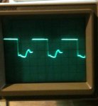
Screen shots from two different oscilloscopes

One is from a Tektronix the other is a Picaxe based small oscillo. The probe was connected to the output of the infrared sensor and to ground.
 

Attachments

Last edited:

Dippy

Moderator
That's nearly very good. As long as it works that's good. Up to you to spend some time cleaning it up if necessary.
 

MFB

Senior Member
From the trace it looks like the sensor is not able to pull its collector down to ground (e.g. not saturating) and this may cause multiple counts per pulse. As the pulse rise and fall times seem reasonable you should be able to increase the collector resistor, to achieve saturation, without rounding the edges too much.
 

Armp

Senior Member
From the photo of your setup it looks as if the 'white' sector of your disk is in fact mirror like? You may find that painting it white or adding white tape will work better as it may actually 'scatter' more light back to the detector.

Also check the spacing as the sensitivity drops off quite rapidly if not 0.15".

From the spec:
ScreenShot.jpg
 
Top