Powerup and detect switch

ciseco

Senior Member
Hi all,

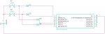
Wanted to run this by those who know better if it would work. All I want to do is power up the PICAXE and detect which switch was pushed, it doesnt matter that the circuit dies after being released. Simply circuit attached.

Would welcome any thoughts

Cheers

Miles
________
Mercedes-Benz W125 specifications
 

Attachments

Last edited:

ylp88

Senior Member
Make sure you include a pull-down resistor on the SERIN pin (or keep the programming interface) and place pull-down resistors on each of the input pins as well.

You might want to add a filter capacitor after the switches as well to ensure that the PICAXE powers up only once instead of fluctuating in an unknown region if the switches make poor contact or experience bounce. I assume you will save the result to the onboard, non-volatile EEPROM, which may require some period of stable time in order to save the data.

ylp88
 

BeanieBots

Moderator
You'll need pull-down resistors on the inputs. Other than that, it should be OK. Bear in mind that a typical startup time for a PICAXE is 76ms so you will need to hold the button down for more than just an instant.
Might also be a good idea to add a little bit of capacitance to the PICAXE power rail. Above and beyond the normal decoupling which you were going to add anyway, weren't you?
 

ciseco

Senior Member
Sorry guys, was essentially a back of a fag packet drawing, so hadn't included any other parts, good of you to draw attention to it so as not to confuse others, and bad of me for not including it initially.

I didn't allow for bounce, good point.

If I was to get rid of the interface would a 47K do or should it be closer to the 22K+10K?

It would draw 60ma @ 3v for about 1/4 second, I'm guessing that'll be one big cap?
________
Yamaha RD56 specifications
 
Last edited:

ylp88

Senior Member
47K will probably be fine, but 33K is a preferred value which is closer to what you should have.

With so many extra outputs, perhaps you can design something which basically allows the PICAXE to latch the power supply on, perform the desired operations and then power itself down...

ylp88
 

hippy

Ex-Staff (retired)
Bounce is the real issue here and that extends to putting caps on the power rails and inputs. Adding those caps could actually make things worse by keeping the PICAXE powered by parasitic supplies even when the battery is disconnected. If that happens then you could lose subsequent resets and it's more likely to be in that 'neither here nor there' state ylp88 cautions about.

I'd actually go the oposite direction, no caps and a low(ish) R across +V to 0V to get any parasitic power drained off quickly. I don't think any bounce and powering up and down will have adverse effects.

And it all seemed such an amazingly simple concept. Best get the breadboard out and start prototyping :)
 
Top