Picaxe Output pin Voltage

ROYMARNEWICK

New Member
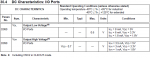
I am not sure whether I am blind, stupid or just being a numpty (or some combination of these). I have been working on the assumption that the output pin voltages are equal to the power supply voltage as, despite numerous attempts, I have not been able to confirm this from the Picaxe user manuals.
Can someone :
* clarify / confirm what the output voltage is?
* advise where I can read this info in the User Manuals as I am someone that likes to see things in a definitive form e.g. data sheet / manual etc.
 

papaof2

Senior Member
Any voltage that goes thrugh a switching device (output transistor) will potentially have some drop as most chip components are not zero resistance. Whether that voltage drop will be significant in what you're doing with the chip is primarily determined by the current handled by that pin.
 

Flenser

Senior Member
ROYMARNEWICK,

The piece of information you are missing is that Rev-Ed do not make the chips. Rev-Ed take PIC microcontroller chips made by Microchip, program them with the PICAXE firmware and then sell those as their PICAXE chips.,

So all the electrical specifications for the PICAXE chips are in the datasheets for the Microchip PIC chips.
You can find which PIC chip is used for which PICAXE chip on this page PICAXE Chip Labels - What is PICAXE? which also has a link to the PIC microcontroller datasheets.

In the Microchip PIC datasheet you search the sections for the electrical specifications to find the one you are looking for.

The 08M2 chips uses the Microchip PIC12F184 microcontroller and section 30.4 DC Characteristics: I/O Ports gives these specs for the output voltages:
25655
 

hippy

Ex-Staff (retired)
It can get quite complicated. Very few microcontroller or other output pins are ever exactly at 0V or at the power rail, are usually somewhere 'close to them'. For the 08M2 as Flenser shows; an output low will never be higher than 0.6V and an output high will never be less than 0.7V from the supply.

That however is with nothing connected to the pin. With a resistor or load between the pin and 0V the output high voltage can decrease. With a resistor or load between the pin and the supply the output low voltage can increase. The lower the resistance, the more current is drawn through the pin, and the more it will change from its 'nothing connected' level. The datasheets usually have graphs for 'output voltage versus current drawn'.

In most cases this isn't a problem. When connected to another chip's inputs what that recognise as high or low is usually 'closer to the middle' so it will usually read an output pin correctly even if the voltage is closer to that middle than might be expected. It's a bit like a person signalling over a distance with flags; even if it's expected they will have the flag fully up or down you can usually tell if it's an up or down even if not fully.

What this means is that it usually doesn't matter what the voltages are because it will usually just work as expected, no matter what that voltage is.

Where the actual voltage does come into play is if you are using the output as a voltage rather than as an input into another chip.
 

ROYMARNEWICK

New Member
Thanks for your detailed explanation - good analogies presented.
In my present situation, I did need to know the likely output voltage but understand that in many applications this is of no significance.
I am now fully prepared for battle!
 
Top