Picaxe-based dual-channel PC oscilloscope

womai

Senior Member
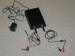
Finally found time to assemble the complete unit - enclosure, connectors, professional PCB. Attached below are a few pictures and screenshots.

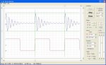
The scope is working like a treat - sample rate up to 1 MSample/sec, usable analog bandwidth up to approx. 200 kHz (limited by sample rate - the raw -3dB bandwidth is around 500 kHz). It has everything a "real" scope should have (with the exception of AC coupling) - range from 1V/div down to 20mV/div (20 divisions, i.e. twice as much as a "standard" display, so maximum range is 20V), offset control, different timebase settings, trigger on channel 1 or autotrigger, trigger level and polarity control, etc. Measurements are done with the cursors (also shown in the screenshot). With a single channel and short record (125 points) the screen update rate is close to 10 frames/sec, less with full record length (250 points) and dual channel, but still very usable.

The basic PC software is finished, although there is still some room for improvement - I am thinking of adding gain/offset calibration (will make the absolute level display more accurate), real-time FFT to show the signal's frequency spectrum, and setup save/restore.

The screenshot shows the scope in dual channel mode - channel 1 displays the 10 kHz trigger signal from my signal generator, channel 2 displays a damped sine wave produced by this generator (sine wave frequency is 100 kHz).

As to the hardware, the jumpers (red) allow to use either the MAX153 or the ADC0820 as the scope's ADC - the latter has a lower nominal sample rate (400 kS/sec, as opposed to > 1 MS/sec for the MAX153) but is second-sourced and seems to be easier/cheaper to acquire if you can't get them as a free sample. That said, I got a few ADC0820's from Maxim and was able to run them up to 1 MS/sec without any problems.

Wolfgang
 

Attachments

Last edited:

womai

Senior Member
Picaxe based oscillsocope - screenshot

Found out I can only attach two images to a post - so here is the screenshot I mentioned before.

The screen colors are actually much brighter than the screenshot indicates - I only had Paint available to convert my BMP file to JPG, and it did not do a good job rendering the trace colors (red, green and blue).
 

Attachments

Last edited:

Andrew Cowan

Senior Member
That has to be the most impressive thing on this forum. The software looks amazing!

To sum it up, I can only agree with smokelight101.
 

womai

Senior Member
Actually I am looking for a way to make the scope available as a kit (PCB plus parts). I believe this will be much better value than just the bare PCB - many of the parts (e.g. the 74xx logic chips) have minimum orders of >=10 if you want to get decent pricing, and you just need 1 each. Same goes for the PCB (becomes very inexpensive at around 100+ pieces). So I think a kit through a distributor - which can drive cost down through quantity - will cost significantly less than procuring all the components yourself (not counting the time spent on searching and ordering - I know what I am talking about).

Nevertheless, as I said previously I want to keep this an open design, i.e. schematic, PC software etc. freely available - for that I still need to put the circuit description, bill of materials etc. together, thus give me a few more weeks - so far I have been working to get everything up and running. So if you think you can do it for less yourself - or just like the challenge - then by any means do it.
 
Last edited:

stocky

Senior Member
So it simply outputs via a std PIXAXE programming cable to the pc software?

That is one fantastic PICAXE project!
 

womai

Senior Member
Yes, connection is through the programming cable. This also makes it easy to use a USB port instead - just use the USB programming cable, or the serial cable plus the serial-to-USB converter.
 

demonicpicaxeguy

Senior Member
love it, the whole thing looks very professional, you should not only sell it as a kit but also as a prebuilt unit as well,
i'd maybe look at a usb (hid) interface for it since serial ports are getting rarer and rarer
 

vk6bgn

New Member
I only wanted to post one word. And that was the word Awesome. But the forum prompted me to enter at least 10 words as it said my message was to short. So here it is now….

AWESOME!
 
Incredible! I will buy one the minute you put it up for sale! There is a great company here in the States called SparkFun.com... You should contact them about making a SMD kit version!
 

lbenson

Senior Member
Lovely and impressive piece of design work. I also would sign up for the kit version as soon as available. Then Steve Joblin mentions SMD, which would about make it fit into a 4-AA battery box. A PICAXErs work is never done.
 

womai

Senior Member
To demonicpicaxeguy: USB is already feasable - just use the USB download cable instead. (if somebody does not have a serial port on his/her computer, he will already have this cable available to program the Picaxe. But otherwise the serial download cable is much cheaper than the USB version, and one important consideration was to keep the cost down). The user won't care that behind the scenes it look like a seriaql port to the Picaxe and the PC software. (and the Picaxe is too slow to benefit from the true USB speed anyway).

As to making an SMD version: I thought of it and I could easily do this myself (in fact, I normally do everything except the Picaxe in SMD). About 2 days of layout work. The reason I stuck to DIP & through-hole was that many hobbyists aren't too comfortable soldering SMD components - an important consideration for a kit. I didn't shelve the idea completely - in fact, SMD would not only make the PCB quite a bit smaller and cheaper, but also reduce component cost a little bit (DIP is more expensive than SOIC, and SOIC does not need sockets).

Wolfgang
 

Dippy

Moderator
Mmm... I wonder how much assembled smd boards would cost.

I don't know what Wolfgang's projected sales are, so I hope he does the calcs.
 

womai

Senior Member
I've built three prototypes so far - all of them worked right away so I am quite confident now my design is solid. I guess before any distributor even thinks about carrying this he wants to see and touch a working prototype. I definitely don't want to be in the business of procuring parts, assembling units, and doing the distribution - that would only take time away from designing new things, and also mean a significant financial outlay (as I said, to hit my cost goal I'd need to do around 100 units minimum). Although I may put some of the unused protos (fully assembled and tested) up for sale later (for people on this forum only), since I still have parts for a few more. Anybody interested please contact me offline at gwen.and.wolfgang{at}sbcglobal.net. I'm not trying to make money on those protos, so I'd sell them at cost (parts + actual shipping).

I'll keep you posted when/if there is progress with a distributor.
 

womai

Senior Member
Short update, I found takers for all my surplus prototype units, and I won't produce any more - so if you want one, you'll now need to wait until I found a distributor or find the time to put the circuit description etc. online.
 

Dippy

Moderator
You've done a really impressive job there Wolfgang.

You haven't indicated spec. , size, construction skill required, potential cost for DIY or kit. These things would be helpful for people making a buying decision. Just remember the advertising T&C for this Forum though eh?
 

BCJKiwi

Senior Member
@Dippy'
What are the T&C??

I've always assumed 'commercial' activity would be frowned upon but have not found any Terms and Conditions of use spelled out anywhere - probably just missed them!

Perhaps a link to the Terms and Conditions could be placed in the top menu bar of the Forum - then there would be no excuse for anyone not knowing.
 

womai

Senior Member
Dippy,

when time allows (I'm quite busy in my "real" job right now) I want to put all that info - schematic, circuit description, bill of materials, etc. - online. A lot can already be gleaned from my previous posts on the subject. As I said, it will be an open design, so anybody can go and get the parts and build one himself - you don't have to buy anything from me (or rather, the distributor) if you think you can get it yourself for less. A bare-bones version without enclosure, built up on a sufficiently large protoboard comes to approx. US$50 if you get the op-amps, ADCs, I/O expander and DACs as free samples (Microchip and Maxim) and have to buy everything else, including the 28X1 Picaxe. That does not include probes (grabber cables are sufficient) or the download cable. Although a well-designed "real" PCB helps - my breadboard version had slight issues with trigger stability at very small signal swings because the trigger circuitry produced crosstalk into the signal, making the triggering instable; as I expected those issues are gone with the real PCB which has solid ground fill on the bottom, and separate voltage regulators for the analog and the digital section, respectively.

Skills required - basic soldering - if you can put any of the Rev-Ed kits together, you can do it; all components are are through-hole, all chips are DIP packages. It takes me less than 2 hours to assemble a complete board. I did my best to make it beginner-friendly, thus there aren't any adjustments (e.g. trimmers) to make to get the circuit up an running, with the exception of a jumper that you have to move to download the firmware. Size - the box I put it in is about 7 x 5 inches (approx. 17.5 x 12.5 cm), i.e. less than half a sheet of paper.

Wolfgang
 
Last edited:

womai

Senior Member
Publishing the design is still a work in progress - unfortunately I also have a real job and a real life that do not leave a lot of time for these side projects. I did a second revision of the scope that I am currently bringing up on my bench, and I also made many improvements to the PC software. I am about half way through with putting a small webpage together that will have circuit description, schematic, bill of materials, layout etc. There will be everything that is needed to build your own. I'm also working on making it available either as a kit or as a fully assembled unit.

Wolfgang
 

womai

Senior Member
I have successfully brought up the second revision of the scope. No huge changes but it does add a MAX232 interface (can be left out if desired but allows to use the hardware USART functions of a standard bare PIC). The project webpage is about halfway done but not online yet.

As for the kit, at a minimum I will be able to offer the bare board, which saves a lot of time and headache when putting the scope together. In addition, I am still working to get it distributed either as a complete kit or as a fully assembled unit (from what I have heard assembling and wave-soldering the board won't cost much more than having somebody put together and package the kit).

As I said, my time is a bit limited, so bear with me :eek:

Wolfgang
 

womai

Senior Member
Once the website goes online, I should at least be able to sell the bare printed circuit boards. This is really the component that is very expensive as a one-off and quite affordable in quantities of 50 or more. I'll also put together a bill of materials so at least US based people should have little trouble obtaining all the other parts themselves with limited effort. As for the complete kit (or fully assembled unit), I am still waiting for a further reply from a well-known vendor of a Microchip based line of educational microcontrollers :)

With regards to timeline for the webpage, that can be anything between a few days and many weeks depending on my workload at my real job and in my private life.
 

womai

Senior Member
I have put a website with the full scope design online. A few "details" are still missing at the moment, most importantly the bill of materials and a description of the PC software. But overall I think it should enable anybody to build his/her own.

Have a look and let me know what you think:

http://www.pdamusician.com/lcscope/

Wolfgang
 

womai

Senior Member
Incredible, less than 3 days and already close to 3000 views on Instructables. And they even made it a featured article after their review.

Wolfgang
 

leftyretro

New Member
To demonicpicaxeguy: USB is already feasable - just use the USB download cable instead. (if somebody does not have a serial port on his/her computer, he will already have this cable available to program the Picaxe. But otherwise the serial download cable is much cheaper than the USB version, and one important consideration was to keep the cost down). The user won't care that behind the scenes it look like a seriaql port to the Picaxe and the PC software. (and the Picaxe is too slow to benefit from the true USB speed anyway).

As to making an SMD version: I thought of it and I could easily do this myself (in fact, I normally do everything except the Picaxe in SMD). About 2 days of layout work. The reason I stuck to DIP & through-hole was that many hobbyists aren't too comfortable soldering SMD components - an important consideration for a kit. I didn't shelve the idea completely - in fact, SMD would not only make the PCB quite a bit smaller and cheaper, but also reduce component cost a little bit (DIP is more expensive than SOIC, and SOIC does not need sockets).

Wolfgang
Great job. And I agree SMD for DIY'ers is a real challenge. I know many of mastered it, but at my age the eyes just strain and the hand trembles too much. If I can't build it with DIP then I don't build it. ;)
 
Top