PICAXE 28X1 microcontroller

Mr. I need help

New Member
I have two PICAXE 28X1 microcontrollers and am having trouble getting them to communicate. Basically, one chip is sending a high from pin 15, portc4, to pin 3, porta1 of the other chip. both 28X1 chip are fully functional but neither of them transmit or recieve this high command. What is wrong here? i do not think i am missing anything from my programming as i have successfully recieved a high through pin 2, porta0. Please help :confused:
 

moxhamj

New Member
When you say neither of them transmit or receive this high command, we need to break this down to testing each seperately.

Does it send a high? Put a led and a 1k resistor in series. Connect the led to 5V to test it comes on. Now put the led on the output pin of the 28X. Can you turn it on and off?

Does it receive a high. Set the pin as an input. Connect it to 5V. Does it read a high or low value?
 

BeanieBots

Moderator
To save any confusion, please tell us which PHYSICAL LEGs you have connected together and what COMMAND(s) you are using to do the communiction. Better still, circuit diagram and code.
 

Mr. I need help

New Member
Reply Dr Acula: PICAXE 28X1 microcontroller

the two chips can recieve a high command and output but cannot communicate with each other. First, I'll give you an overview of everything.

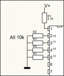
I'm making an air hockey table for my year 12 VCE Systems Engineering. I have a scorebard with 4 seven segment displays, two on each side, showing the score of both players. I have and infrared reciever and transmitter at each goal. When the puck goes into one of the goals the infrared transmitter is switched on, sending a high of 5 volts to physical pin2 to one chip and vica versa.

One chip has an infrared input, 2 seven segment displays, an output to the other chip and an input from the other chip.
The other chip has an infrared input, 2 seven segment displays, n output to the other chip, input from other chip and output to LEDs around the perimter of the table.

Each chip work perfectly as they both recieve a high from their infrared transmitter and the score changes up to 7, however i would like to have all the LEDs around the perimter flash when a player wins except because the chips wont communicate only the chip controlling one of the player's is connected to the LEDs so only when that particular player wins will the LEDs flash for the ending.

So when a player gets to seven I wrote a statement on chip 1: high portc 4
and on the other chip i had if porta pin1 = 1 then Ending, where ending was the flashing LEDs when a player won. I was also going to make the chip star again after this and send a high to the other chip and it would start agian as well.

Sorry if I'm not clear enouhg. So to answer your questions the chips do send highs and also reecieve highs but will not respond to each other. My teacher said something about maybe the one of the chips is making the input pin low so no command will get through. I'm not sure why this is happening as I am using the correct pins. Thanks
 

moxhamj

New Member
Re on the other almost identical thread "Last edited by Mr. I need help : Today at 03:39. Reason: no one was replying" there are now three threads running on this topic - maybe keep it to just one otherwise it will get very confusing.

I wonder if no one is replying because the problem is confusing. I don't understand the problem. Re "So to answer your questions the chips do send highs and also reecieve highs but will not respond to each other"

So a chip can read a high. It can send a high. I presume you mean a high, as in 5V measured by a voltmeter. So how can it output a high and read a high but not work when joined. Does it work when you link two pins with a wire? Do you have a common ground or are there seperate (?floating) power supplies? Do you have leds on those wires so you can see what is going on? Do you mean high as in 5V, or high as in sending some data via serout or some other data protocol?

Sorry, lots of questions.
 

Mr. I need help

New Member
Reply Mr. I need help: PICAXE 28X1 microcontroller

Sorry about all the threads. I wasn't really sure what i was doing as I am new to all this forum stuff.

Ok, PICAXE A and PICAXE B are both powered from a 5 volts regualtor and both have a common ground. When i said "high" i meant sending 5 volts. the tarck on the circuit board is correct so link the two pins with a wire does not change anything.

From another thread someone said that PICAXE B may not be recieving because it is busy. Would this be correct?

I changed my program on PICAXE A to simply send 5 volts to PICAXE B and tested the value of the output from PICAXE A with a voltmeter which was 0 volts. Is there 0 volts on the output because the PICAXE B is busy? Becasue i thought it would stay 5 volts whether the PICAXE B was busy or not.
 

moxhamj

New Member
Good idea - break it down into parts. So you are outputting a high on picaxe A in code, but a high is not appearing on the pin. That certainly helps isolate the problem. Once you make a pin high, it should stay high. What is the code, and which pin do you think should be high from the code?

Sometimes it is the leg that is high rather than the pin. Physical legs and pins are labelled differently. Picaxes start out at the beginning of the program with all pins low, so you could make just one pin high, then run around the chip with a multimeter to see if any other pins are high that you are not expecting to be high.

Just another thought. Is the pin high without picaxe B connected? Just wondering if picaxe A was outputting a high and picaxe B was outputting a low they might be fighting? Try connecting with a 1k resistor between the two chips rather than a wire - then you can test for the status of each pin at the pin even if one was high and one was low.
 
Last edited:

Mr. I need help

New Member
Reply eclectic: 28X1 microcontroller

I look at your attachment that you recently posted with the 10k resistors connected to pin2,3,4,5 all of which i have never seen before. What are these resistors meant to do? Also how can i connect an output from my microcontroller if these pins are connected to ground? Many thanks
 

eclectic

Moderator
Have a look at manual 3,

switch interface.

In simple terms, the pin is at zero volts, until a "high" appears.

e

Please can you post the code you are trying.
 

Attachments

Last edited:

Mr. I need help

New Member
I opened the PICAXE manual 2 but could not find what you were talking about.
From PICAXE A i sent high portc 4
From PICAXE B i sent:

b5=0
b0=0 'score for player0
main:
if porta pin0 = 1 then SevenSeg1
goto Chaser1
if porta pin1 = 1 then Ending

SevenSeg1:
b0=b0+1
if b0=1 then goto Disp0
if b0=2 then goto Disp1
if b0=3 then goto Disp2
if b0=4 then goto Disp3
if b0=5 then goto Disp4
if b0=6 then goto Disp5
if b0=7 then goto Disp6
if b0=8 then goto Disp7
goto main

Disp0:
let pins=%0000
goto main

Disp1:
let pins=%0001
high portc 3
pause 200
low portc 3
pause 200
high portc 3
pause 200
low portc 3
pause 200
high portc 3
pause 200
low portc 3
pause 200
high portc 3
pause 200
low portc 3
pause 200
high portc 3
pause 200
low portc 3
pause 200
goto main
Disp2:
let pins=%1000
high portc 3
pause 200
low portc 3
pause 200
high portc 3
pause 200
low portc 3
pause 200
high portc 3
pause 200
low portc 3
pause 200
high portc 3
pause 200
low portc 3
pause 200
high portc 3
pause 200
low portc 3
pause 200
goto main
Disp3:
let pins=%1001
high portc 3
pause 200
low portc 3
pause 200
high portc 3
pause 200
low portc 3
pause 200
high portc 3
pause 200
low portc 3
pause 200
high portc 3
pause 200
low portc 3
pause 200
high portc 3
pause 200
low portc 3
pause 200
goto main
Disp4:
let pins=%0100
high portc 3
pause 200
low portc 3
pause 200
high portc 3
pause 200
low portc 3
pause 200
high portc 3
pause 200
low portc 3
pause 200
high portc 3
pause 200
low portc 3
pause 200
high portc 3
pause 200
low portc 3
pause 200
goto main
Disp5:
let pins=%0101
high portc 3
pause 200
low portc 3
pause 200
high portc 3
pause 200
low portc 3
pause 200
high portc 3
pause 200
low portc 3
pause 200
high portc 3
pause 200
low portc 3
pause 200
high portc 3
pause 200
low portc 3
pause 200
goto main
Disp6:
let pins=%1100
high portc 3
pause 200
low portc 3
pause 200
high portc 3
pause 200
low portc 3
pause 200
high portc 3
pause 200
low portc 3
pause 200
high portc 3
pause 200
low portc 3
pause 200
high portc 3
pause 200
low portc 3
pause 200
goto main
Disp7:
let pins=%1101
b5 = 0
goto Flashperimeter


Chaser1:
high 7
pause 50
low 7
pause 50
goto Chaser2:
Chaser2:
high 6
pause 50
low 6
pause 50
goto Chaser3:
Chaser3:
high 5
pause 50
low 5
pause 50
goto Chaser4:
Chaser4:
high 4
pause 50
low 4
pause 50
goto Chaser5:
Chaser5:
high portc 7
pause 50
low portc 7
pause 50
goto Chaser6:
Chaser6:
high portc 6
pause 50
low portc 6
pause 50
goto Chaser7:
Chaser7:
high portc 5
pause 50
low portc 5
pause 50
goto Chaser8:
Chaser8:
high portc 4
pause 50
low portc 4
pause 50
goto main:

Flashperimeter:
b5=b5+1
if b5 = 50 then goto Ending
high 7
high 6
high 5
high 4
high portc 7
high portc 6
high portc 5
high portc 4
pause 100
low 7
low 6
low 5
low 4
low portc 7
low portc 6
low portc 5
low portc 4
pause 100
goto Flashperimeter


Ending:
b0=0
let pins = %0000
goto main


Sorry i couldnot attach this as a code as i dont have the program on this computer
 

eclectic

Moderator
Mr I

First, my apologies. It's manual 3, pages 25/26.

I've tried a circuit using the diagram below, and the program below.

LED and 300R resistor on portC 3 (physical leg 14)

It works, both in Simulation and on breadboard.

More apologies for the rushed diagram.
Code:
#picaxe 28x1

main:
if porta pin0 = 1 then disp1
goto main


Disp1:
for b20 = 1 to 10
high portc 3
pause 200
low portc 3
pause 200
next
goto main
To attach, just use the "[" and "code" and "]" and "/"
 

Attachments

Mr. I need help

New Member
OK. Thanks for the tip

I had a look at PICAXE manual 3 and read about the switch interfacing circuit. So is my system not working because i don't have pin0,1,2,3 connected to ground via a 10k resistor? I am also wondering about how to connect this to my circuit.... I looked at the image posted by eclectic with the push-to-make switch connect to 5volts the 10k resistor to ground. Do i have to add a switch, as i am not sure how to configure it with my system?
Where would i connect the output pin from PICAXE B?
 

eclectic

Moderator
OK. Thanks for the tip

I had a look at PICAXE manual 3 and read about the switch interfacing circuit. So is my system not working because i don't have pin0,1,2,3 connected to ground via a 10k resistor? I am also wondering about how to connect this to my circuit.... I looked at the image posted by eclectic with the push-to-make switch connect to 5volts the 10k resistor to ground. Do i have to add a switch, as i am not sure how to configure it with my system?
Where would i connect the output pin from PICAXE B?
No need for a switch in your final circuit; just connect your Picaxe B output,
via a 1k resistor, as suggested by Dr. A.

Might I very seriously suggest that you breadboard the basic
circuits first.
Start with simple circuits and simple programs.

Then build from them.

e.
 
Top