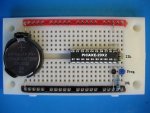
PICAXE-20X2 released.

manuka

Senior Member
Down here in the shakey isles of NZ, both Andrew Hornblow (near New Plymouth) & myself (Wellington) now have our hot little hands on some 20X2s, & evaluation loan outs to fellow Kiwis may be considered.

Andrew, who has already begun fleshing out his Picasa 20X2 pages => http://picasaweb.google.com/picaxe/PICAXE20X2# ,notes the 20X2 bank pins can be simply & conveniently addressed 0-16. Is this documented?
 

Dippy

Moderator
IP - tee hee, don't take the Micky :)

You must admit that the breadboards look like they're new or well cleaned.
And it looks like Stan's got new felt tip pens, hook-up wire (not coiled up in a heap) and maybe even a new camera(?).

I must say (seriously) : Nice sharp photos Stan. Much better than the older productions. New camera? New glasses?

We'll be seeing a lot more of them ... no doubt ;)
 

hippy

Ex-Staff (retired)
the 20X2 bank pins can be simply & conveniently addressed 0-16. Is this documented?
No, that's not documented. Primarily because we do not wish to encourage use of numbered pins on the X2 range, the preference being letter.digit. There are reasons for that -

The number to letter.digit mapping may vary between PICAXE variants leading to code which is difficult to port to a different device.

When people see "High 8" and the like, the first instinct is to assume a typo error. If people post problem code, "I use high 16 and my motor does not turn", it's not immediately obvious what "pin 16" is, which PICAXE is being used, which may mean a long back-and-forth Q&A session before starting to even consider the actual problem.

Similarly with "Input 0", "ReadTemp 0,b0" etc, the first instinct may be to assume PICAXE 08M, and pin 0 is output only.

The correlation of pin number to analogue channel number no longer exists on the X2 which can add another layer of confusion when using numbered pin; "High 3:ReadAdc 3,b0" on first sight appear to use the same pin, on pre-X2 that may be so, but not on the X2's.

Seeing numbered pins in code may lead to others simply changing #PICAXE definition and expecting code to work. It's impossible for a reader to subsequently tell if the numbering is as intended or left over from earlier PICAXE work.

The potential for confusion between pin and leg numbering becomes even greater.


Use of letter.digit shouldn't prove to be any more complicated than using numbered pins. It is still possible to use indexing to access individual pins ...

For b0 = B.0 To B.7
High b0
Pause 1000
Next

Multi-PICAXE setups, say where a sender sends "pinNumber, zeroOrOne" to control an output in a output extender PICAXE may need the abstract pinNumber to be re-mapped, but this is relatively easy ( just an example, hardware may differ ) ...

Tx:
SerOut PIN, BAUD, ( 8, 1 ) ' Set LED 8 On

Rx:
SerIn PIN, BAUD, b0, b1
Select Case b0
Case 0 To 7 : b0 = b0 & 7 + A.0
Case 8 To 15 : b0 = b0 & 7 + B.0
Case 16 To 23 : b0 = b0 & 7 + C.0
Case 24 to 31 : b0 = b0 & 7 + D.0
End Select
If b1 <> 0 Then
High b0
Else
Low b0
End If
 

manuka

Senior Member
Hippy: Thanks for the lucid followup. I sense there may be short cut users who'll need "persuading"!
IWP & Dippy: Those Picasa 20X2 pix are Andrew's (via a 2006 era Canon A530-identical to my own).
 

hippy

Ex-Staff (retired)
Hippy: Thanks for the lucid followup. I sense there may be short cut users who'll need "persuading"!
We obviously cannot prevent PICAXE programmers doing whatever they want ( though we could invalidate syntax for commands which use number where letter.digit is preferred ), but I'd suggest those contemplating using numbered pins on an X2 reflect upon what they are actually gaining from doing so, and what potential for confusion and later problems they may be creating for themselves and others.

Perhaps one way to look at it is as counter to protocol and convention, on a par with using 'txt spk' instead of English in the forum. Just because you can, doesn't mean you should. Just because it works, doesn't mean it's best or desirable.

There may be cases where numbered pin references on X2 have their place and are the best way to deal with a coding issue and there's good justification for doing so. I believe that should be the special case rather than the norm, and well documented to explain what the code does and why.

From a 'Professional Programming' perspective, except for short example code and snippets, pin references ( like variable names ) should be made meaningful through SYMBOL statement definitions so there should be minimal references to any specific pins within the code itself. A SYMBOL name equated to pin number rather than letter.digit doesn't have any real advantage only disadvantages.

My thinking on this is relatively simple, if it's not beyond all doubt known if 'pin 8' is on port B or C on a 20X2, is on port A, B C or D on a 40X2, it's just creating extra work for yourself and others who read the code for no good reason. Brilliant and useful code could easily be rendered near inaccessible to others. Just like writing documentation in Sanskrit I'd recommend not doing it. But every programmer has to decide for themselves.
 

Dippy

Moderator
Personally, I much prefer the letter.digit format.

Less ambiguity.
More 'obvious'.
Closer to format used by many other compilers.

A sensible forward step, well done.

Something else has perplexed me for a while:-
The DIRS command.
Like Stamp you set a bit to make it an output.
So:-
let dirsB = %00000011 ‘ switch pins 0 and 1 to outputs

That's fine when you get used to it.

However, PIC TRIS is the opposite
TRISB = %11111100

Just from a word-association-football thing 1 looks like I for input , and 0 looks like O for Output. Making the thing instantly readable.

So, was merely wondering, and it's probably historical, why invert it? And do we 'blame' Stamp? :) (kidding).

Not important .. it's just 'out-of-interest' as I can't see the logic (haha)/sense.

Maybe it's only me that thinks 1 looks like I-nput etc.... :(
Oh dear.
 

hippy

Ex-Staff (retired)
Yes, it is for historical reasons and probably because 'things naturally default to zero', so the logic follows that a default of 'dirs' to zero matches a default to inputs, to set an output, set a one.

I too trip over the 0 = O(utput), 1 = I(nput) used by TRISx on PICmicro, and that's exactly how I visualise it as well. At least we use DIRSx, but I have made the mistake of treating DIRSx as TRISx. I think it's what one's most familiar with.

A 'trisc' is implemented on the 20X2 but no 'trisb'. I will investigate that.
 

manie

Senior Member
As a relatively new Picaxe user, I immediately saw the benefit (for myself) in the "Letter.Digit" system. It makes it clear EXACTLY which pin you are addressing and will even persuade you to at least LOOK at the pin-out drawing to make sure. I like it.

As for x1's and using "Symbol xxx = Pin", like "symbol LED1 = 1" or "symbol Sout = 0", I have now discovered the friendliness of this in your own program. Makes addressing the output etc. so much easier.

I think the X2's are on the right road, well done Rev-Ed.
 

hippy

Ex-Staff (retired)
As a relatively new Picaxe user, I immediately saw the benefit (for myself) in the "Letter.Digit" system. It makes it clear EXACTLY which pin you are addressing and will even persuade you to at least LOOK at the pin-out drawing to make sure. I like it.
The only cautionary note there, to those familiar with PICmicro, is the datasheet to look at for pinout is PICAXE Manual 1, and not the PICmicro datasheet.

The pinout has been rationalised for PICAXE use with C.x on the left and B.x on the right, in keeping with previous 14M and 20M conventions of one port on left, one port on right.

Due to the way the PICmicro chip is laid out ( which we have no control over ) the PICAXE port letter.digit is not the same as the PICmicro port labelling. Untangling this convolution is automatically done within the PICAXE firmware so most PICAXE users will not have to concern themselves with the mapping nor have to give it a second thought.

The rationale for doing this was to make the PICAXE 20X2 more useful and more easily usable than otherwise. When we refer to PICAXE X2 ports, the terminology will by default refer to PICAXE port naming conventions as described by pinouts in Manual 1.
 

Dippy

Moderator
Good reminder hippy, especially for those who switch between devices...

Ah... the PICAXE+breadboard / Kiwi-Patch-Board images have started.... :)
 

hippy

Ex-Staff (retired)
... and what value is that resistor ?

The standard 22K would be red-red-orange ( or red-red-black-red AFAIR for 1% ).

The 10K pull-down isn't essential unless the PICAXE needs to operate when the download cable is disconnected, it simply stops the Serial Input floating high and randomly resetting the PICAXE when it perceives a download is being initiated.

Not really a problem if the PICAXE circuit will only ever be used when connected to a PC.
 

mh108

New Member
The 10K pull-down isn't essential unless..., it simply stops the Serial Input floating high and randomly resetting the PICAXE when it perceives a download is being initiated.
Just a thought...

Could this be a cunning method to reset a picaxe (those without external reset pin) ? Some kind of transistor/resistor combo to pull the pin high if you wanted.......

Would this be reliable?
 

hippy

Ex-Staff (retired)
Yes, it's a cunning method indeed; the Serial In leg can be connected via a diode ( 1N4148 etc ), pointy end to Serial in, and the other end to a PICAXE output pin which is set high to reset the PICAXE. The 10K/22K interface can usually be left in place.

This is not a true reset and there will be a time delay while the PICAXE is figuring out that nothing is really happening, no download is actually taking place. It also won't work if SERRXD or DISCONNECT has been issued, or if the PICAXE pin doesn't reset to input or output low once the pin has been set high.

Code:
TX <----------------------------------------.
                              .----_----.   |
             ___              | +V   0V |   |
RX >----.---|___|---.-------->| SI   O0 |---'
       .|.   22K    `---|<|---| X4   X1 |
       |_|                    | I3   X2 |
       _|_                    `---------'

#Picaxe 08M
#Terminal 4800
Pause 2000
SerTxd( "I have Reset", CR, LF )
Do
  Pause 2000
  High 4
  SerTxd( "Failed to Reset!", CR, LF )
Loop
 

manuka

Senior Member
Glad to have prompted this reset brain storm, but the KPB above most certainly does have both resistors fitted. Look closely -the 22k is somewhat obscured by the towering 20X2 socket! Check the more lucid breadboard version for comparison. This follows our long standard 08M layout, which is much used "down under". Stan.
 

Attachments

Last edited:

Texy

Senior Member
Your eyes are way better than mine then!
Actually they almost definately are, but I can't see any other resistor on that pcb!
 

tater1337

Member
Glad to have prompted this reset brain storm, but the KPB above most certainly does have both resistors fitted. Look closely -the 22k is somewhat obscured by the towering 20X2 socket!
by the socket? it's on the other side of the board!

hint. follow the wires, two seem to go nowhere, and make perfect sense if there is a resistor there
 

hippy

Ex-Staff (retired)
I can see it now, and it's logical as Serial In has to get to that ( left, top here ) side of the chip somehow !
 
Top