Picaxe 18X Freeze / Locks up

Adiman

Member
Hi Guys,

I have a real problem with Picaxe 18X locking up/resetting itself mid program.

The circuit itself is a maximum power point tracking solar regulator - basically an efficient buck dc converter with a constantly rapid changing duty cycle.

The picaxe itself is on the low voltage (battery) side of the circuit it controls a high speed opto coupler (HCPL2601) which connects to a tc4422 gate driver ic, and n channel mosfet, on the 'solar panel' side of the circuit powered from a seperate voltage regulator. The picaxe keeps track of the battery voltage by a resistor network and monitors amperage going into the battery using a max4080sasa current sensing IC. The Pic chip itself is on the very corner of the PCB board inches away from the main switching fet, and the Main Inductor.

In usual operation on a bright sunny day the input solar panel side might hover around 32v and the battery side 25v.

The circuit works very well, however when switching 5 amps and above the picaxe continually 'freezes' or 'resets' - a flashing LED will suddenly stay on, or turn off and stay off. Sometimes the PWM output will continue to run at a set duty cycle, sometimes it's off completely. The picaxe sometimes recovers, but often doesnt. This problem can also be replicated often by just touching a Multimeter probe on the +v pin and tapping it a few times (the other end of the multimeter probe not being connected to anything).

The picaxe is powered by a LM2936HV, only pulling 5ma or so maximum, there is a 0.1uF ceramic cap across +v and ground, along with a 22uF Low ESR cap. There is also a 6.2v Zener across these pins to prevent spikes to the chip

To try and stop this random freeze/reset I have so far:

- put a 1K ohm resistor on the reset pullup line along with a a 0.1uF ceramic
- put a 4K resistor across pin 3 and ground.
- put 10k resistors on unused pins to ground
- put a 1000uF low/esr cap next to the chip
- put a freewheeling high speed diode from +v to ground
- put a little metal cover across the chip (bent aluminium)
- changed the Picaxe chip for another
- modified the program heavily
- soldered directly to the chip instead of a holder
- Monitoring the voltage across +v to ground stays at 5.00V
- Monitored the current being pulled by the micro, never more than 5ma
-The picaxe outputs are only connected to a maximum of a 500 OHM resistor (which drives the opto). with two leds connected to 3K resistors online.
- I have watched the inputs from the resistor network and max4080 chip with a multimeter, never even getting above 3vots

I'm fast running out of ideas at this stage. It's obviously some sort of static/spike/feedback issue, but i'm at a loss to prevent it, any ideas would be very *very* appreciated!

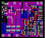
I should note the dc converter is of my own design, and the board is a professionally etched dual sided board with 2oz copper also designed by me.
 
Last edited:

moxhamj

New Member
Seems you really have tried everything. Only doing this at over 5A might be a clue. I have a picaxe driving a mains powered relay, and even just running the mains cord physically near a picaxe will cause resets. This is true even on seperate power supplies. It is especially true when the mains cord is carrying more than 5A. Current seems to matter a lot more than volts. I have yet to find a solution - it is almost as if the electromagnetic pulse is doing the resetting. My working theory is that valves are very immune to EMP, digital chips are quite immune and picaxes are not so immune. My solution is a hybrid of keeping the picaxe over 1 metre away from power leads and also switching using a cascade where the picaxe trips a 555 and the 555 turns on a relay which turns on the mains.

My theory on EMP is further supported by problems I have had with picaxes driving RF transmitters that are over 500mW.

The 555 isn't going to work for you as you are switching high current at fast rates.

In general terms I think the answer is to have the picaxe physically and electrically isolated. Maybe a metre away. And to pipe in the switching information in a way where RF and the like can't get back up the wire. That might mean picaxe=>digital IC chip (HC04 etc) => wire => HC04=>switcher. It might even be picaxe=>max232=>twisted pair wire=>max232=> switcher. Seperate power supplies. If you are really desperate, I've even thought of replacing the 1 metre of wire with fibreoptics.
 
Last edited:

Dippy

Moderator
Without a schematic and code it is very difficult to suggest much.
I'm doing a similar thing, except at 12V.
6 Amps are no prob. You if you scope the S/Mode output there are some juicy spikes.

I use caps on the voltage feedback res network (pot/div) to get attenuate some unpleasant transients getting back to ADC.

Have you checked the 'ground' to the chip? (The quality a well as the track resistance?) Nice fat tracks.

Have you tried a ceramic 47nF or bigger right next to PIC power pins?

The only problems I had was if I updated PWM too fast , then it went mad.

Is it freezing at the same place in code under the same conditions? Have you left an input floating and your code looks at it? Something left over from prototyping or testing?
Or is the code resetting?
You must nail this.
 

Adiman

Member
I should add that there are low/esr caps on both the input and output of the dc converter 2000uF 50v, to mostly stop ripples...

interesting you think the fast changes of duty cycle might cause this issue.... i'm running the frequency at 60khz, (8mhz mode), which gives a duty cycle steps of 138 (0 to 100%) - I estimate it's changing the duty cycle 5-10 times a second - I may have to experiment with the pause length in between this. I do have a lower limit of changes it needs to make before it really doesn't 'track' adequately however.

The picaxe is rock solid when the dc converter is not running i.e duty cycle = 100%

Without pasting the whole program - it's fairly simple, measures voltage/amperage,
50 repeated readadc cycle of each to get a good accurate average value, and compares it to the last value, if amperage is going up, then keep incrementing the duty cycle in that direction until a loss in amperage is found, then change the direction of duty cycle.

Due to the unusual nature of just being able to tap the V+ pin with my multimeter and having it 'lock up' in the exact same way it does as amperage gets higher, I would assume it's not program related, at least not directly.

There are no serin's serouts or anything very complex going on in the progam. just led's getting turned on and off, pwmout to pin 9, and another opto output on pin 8

three inputs have 10k resistors dragging up the voltage, and a dip switch to send it back down again.
 

MFB

Senior Member
It might help to think of the PICAXE as a radio receiver (in a very small plastic box) and the relay as a spark gap transmitter, then apply all the standard noise suppression techniques. For example, mount the PICAXE board in a screened metal enclosure and feed ALL power and I/O via feed-thru capacitors.
 

kevrus

New Member
Due to the unusual nature of just being able to tap the V+ pin with my multimeter and having it 'lock up' in the exact same way it does as amperage gets higher, I would assume it's not program related, at least not directly
are you rerferring to the V+ pin on the 18x? If so, could you possibly have a dodgy 18pin IC socket? (I know, a stab in the dark)

Another thing that I might try would be to replace the converter with a dummy resistance load that will draw at least 5A and see what happens then...

You could also try breadboarding the circuit and try different component/wire positions as the problem may be PCB track layout issues
 

Dippy

Moderator
Oh 5 to 10 times per second is OK. My prototype was doing it hundreds of times per second when it went mad.

Being able to mess-up by touching the V+ of the PIC suggests induced interference, poor grounding, inadequate decoupling or as Kevrus suggested a poor ic/socket/pcb connection.
But without seeing/testing your PCB layout/schematic it's impossible to comment on that.

The low ESR caps will 'absorb' a lot of ripple but they will NOT stop the HF spikes. And these will get bigger as you increase the load. You could put a million uF on it and it won't get rid of it. Check this out with a 'scope if you don't believe me. All the LCRs of your PCB tracks/components will have some effect on signal resonances as a result of the switching.

My PIC is about 3cm away from the MOSFET Driver/Power MOSFETs/Inductor and has no issues. It is unscreened but has a ceramic 47nF cap // 10uF tant cap right next to the i.c. power pins.
 

kermet

New Member
Hi there, there's a couple of things that come to mind straight away.
1. The Picaxe is supplied by a LM2936HV, which is capable of 50mA http://www.national.com/ds/LM/LM2936.pdf

2. The picaxe is driving an opto coupler (HCPL2601) which has an average current of 50mA (each channel), this would bring the total load above the power supplies 50mA capacity.
http://www.datasheetcatalog.org/datasheet2/8/0uk7dopr6lrtokqo46ahpkr6fcyy.pdf

3. I had problems in the past while trying serial commands of the chip doing funny things, as your finding with the PWM command i fixed this by tying all the inuts that aren't used together and to ground, fixed all my issues and do it every time i do a project using serial commands.

Rob
 

Dippy

Moderator
But we haven't got a schematic kermit.
The Data Sheet says the input High will work down to 6.3mA.
We don't know how it is connected to MOSFET driver. And the driver chip needs mugger all so the load won't be high.
We don't know about track lengths, widths or proximity to power tracks.

Personally, unless there is something else needed, I can't see the point of it when using the TC4422 driver which can drive MOSFET from CMOS/TTL control.
I connect straight from PIC to driver via a 220R res , and that res is only there to make me feel happier.

If it is a sensitive commercial design then we've got a problem helping.

Whoa, I've just thought:-
How have you connected the driver chip?
It can only stand up 18V according to Data Sheet.
Are you powering it from the LM2936?

In fact I've just re-read the first post and realise I don't understand it at all. A separate voltage regulator on the solar side?
I had wrongly assumed you were using a buck to convert solar panel V down to a manageable V/I to charge. I think I've misundertood.
I think I'll give this a rest until a schematic is forthcoming as I've lost the plot completely. (which will give me a chance to finish my own :) )
 
Last edited:

Adiman

Member
Could be a ground plain issue I guess, but I took lots of steps to try and negate this problem - including thick 2oz copper tracks, and measurements show miniscule voltage drop or measured AC voltage. I also took steps to keep these plains away from the inductor.

My earlier prototypes on breadboards / veroboards never showed the problem - however I never ran them on high amperage loads...

It's not a pin holder issue, i'd already tried soldering the picaxe directly to the PCB, no difference ...

The reason the HCPL-2601 is there, is because the input side has an earth that is at a different potential due to the switching mosfet in the ground (-) side - probably sounds like an unusual design, but it is in fact the simplest design for a true tracking power tracker

The HCPL-2601 has a 500 ohm resistor in line with it.... which means a max of 10ma drained out of the pin. The voltage reg shows 5mA load
 

premelec

Senior Member
Not having any actual schematic or PCB layout I can only suggest - since you refer to a ground plane - you may have trouble from PCB capacitances between upper and lower copper - if it's a two sided board... Tie your unused 18x inputs more solidly to chip package ground as well rather than using 10K...they may pick up a capacitive coupled spike... good luck with the project!
 

Adiman

Member
Thanks for your help / ideas - I have tried the further few things

-4.7K resistor to ground on all inputs

-tried improving the ground plain

1000pf cap on the resistor network adc input pin

-tried modifying the program to run MUCH slower (2 duty cycle changes a second)

- and finally disconnected all the adc inputs and ran the program with some known constants - same thing occured

It's got me beat - The RF from the switching fets or inductor must be causing it, but I just can't stop it from happening!
 

Dippy

Moderator
Nasty back EMF from the inductor? (Clutching at straws)

In a previous project of mine I had to use a 47R/100uF lowZ combo to the power pin of a PIC to prevent SMPS spikes getting through.

In my latest one I just have the parallel cap pair on the PIc's V+ pin. No probs.
Though I have been very enthusiastic about keeping signal/power tracks apart. And the power-to-the-PIC track is miles away from the MOSFETs and reactive components. I have no groundplane near the inductor, but very wide power tracks.

But, without schematic, photo of tracks etc. I am at a loss to suggest anything to you, though I'm sure you realise it's your circuit (design/component choice/pcb layout) and NOT the PICAXE :(
 

kevrus

New Member
If possible, try an opto-isolator and a separate power supply to drive the FET and converter or as I mentioned before, try using a resistive dummy load (this is what I would try next).
As Dippy said, posting your schematic and board layout may help locate the problem...
 

Unit042

New Member
I'll chip in and try a bit....

"The picaxe is rock solid when the dc converter is not running i.e duty cycle = 100%"

Maybe something inside the DC converter is causing lots of RF.

Perhaps, instead of encasing the PIC in aluminum, try putting it around that inductor.
 

moxhamj

New Member
My theory is a bit rusty here, but inductors store magnetic flux, and RF waves (and light etc) are electromagnetic. Ie they have a magnetic component. Does shielding with metal shield out the magnetic component of the wave? I think this has something to do with absorbing energy through eddy currents, but I don't know how that relates to the frequency of the magnetic pulse.

Picaxes seem susceptible to these pulses, and even if you do get it working, you wouldn't want to inadvertantly get it working so it happens to be only just working, then fails out in the field. I'm not sure I have all the answers here as I'm still working on the problem.
 

BeanieBots

Moderator
As has been stated many times, without a diagram it is hard to guess.
However, the clues are all there. The biggest is that touching a pin with a multimeter wire (aerial) exagerates the problem.
Try fitting a high frequency snubber network to the buck converter switch node. Also doubel check that the core power diodes for the converter are fast ones. If they are not, then very extreme voltages may appear before they start to conduct during inductor off times. Again, snubber networks (if correctly fitted) will help but it is always better to prevent the problem than to try to absorb it later.
As stated by Dippy, adding millions of Farrads will NOT remove all the noise/ripple at higher frequencies.
 

Dippy

Moderator
Hey BB, you're back. How's tricks?

My own solar charging SMPS pcb has been up and running for 15 days now with wires hanging out going to measuring devices (1 scope and 4 DMMs) with no probs. I'm not bragging, I'm just saying that if you get it right then it'll be great.

Dr_Ac. There are some painful current spikes kicking around with S/Mode. With a standard buck design you are dumping a current into fat capacitors via an inductor. There are high currents briefly. The magnetic field around that inductor will change rapidly at that point and during collapse too. So, currents can be induced in tracks passing near the magnetic fields. Obv this is reduced hugely if you use toroidals but most cheap designs will use one of those short fat inductors simialr to those made by Newport. So there will be some RFI and EMI... more TLAs eh?
(Anyway, you know this already, I think you are being a tease:) )

Personally, I think we're going to spiral into guessing games without a schematic and/or artwork layout. AND also input/output capacitor spec. which is very important. Especially as the grounding arrangement sounds unusual and good grounding is CRUCIAL.
Is it your design or a modifed version of someone else's (i.e. is it a blind copy or a modified copy or completely your own orginal work?)

I assume as that is not forthcoming then this is a commericial project?
If so then we're all a bit snookered unless we're on a %age commission ;)

In the meantime I shall touch my +v to see if I can make it crash.
 

Adiman

Member
After much testing, with every combination of resistor/cap/diode - and killing 2 picaxe 18X's out of impatience - I am pleased to note I think I have found a workaround.... a bizarre one at that...

soldering a 47uF L/ESR cap directly on top of the Picaxe across the +V and Ground pins seems to have done the trick, the odd thing is...I had already soldered the same cap directly to the bottom of the board on the same pins, albeit when the IC holder was in place... I had soldered the picaxe directly into the board with a 0.01uF ceramic on the power pins underneath but that hadn't worked! As stated there is already a 22uF L/ESR cap right at the top of the chip...

The DC converter is my own design (as is the whole circuit) - based on standard simple buck topology.

- self-wound toridial inductor (ferrite), sits vertical leaning off the top of the board 20 amp 20uH- 4 large caps almost act as a partial aluminium RF shield- .
- dual mbr2045 shottkys in parallel as the flyback diode
- IRF2805 mosfet as the switching and reverse configured mosfet-blocking
- 2 x LM2936HV regs, and one LM317HV reg to drive the gate driver IC

It's been designed as a part time hobby over 3 years, being fascinated by solar panels, and efficiency... many many different designs and lots and lots of testing...

The converter itself is very efficient, upwards of 97% over 1-20 amps (peak 98%) in 24 volt mode, and (peak 97%) in 12 volt mode..... I have tested it extensively, uses only 25mA operating.

I dont really have a schematic, just a bunch of components jumbled on a blank page in Eagle, since my spec changed so much prototyping over the years I gave up on maintaining a schematic, but here is a pic of the board design, note the component names/values aren't all as stated:
 

Attachments

Last edited:

BeanieBots

Moderator
Well it looks like you know what you are doing.
If such a large cap close to the chip fixes the problem, it sounds like power rail collapse caused by noise.
Double check your ground paths to make sure no high current is common to the PICAXE 0v. Might also be worth further decoupling the PICAXE with low value resistors in series with the power pins.

I still maintain that prevention is better than cure.
Get a good 'scope and try to find the source then prevent the generation rather than try to stop it getting into the PICAXE.

Congratulations on such a good efficiency over such a wide range. The efficiency is not so hard but getting it over that sort of range is something you should be very proud of. Well done. Snubbers will drop the efficiency slightly but should make it more robust.
 
Last edited:

Adiman

Member
To be honest I think my board could use a lot of design changes now that this episode has occured... I had designed the board for DC converter efficiency and really ignored the picaxe, stuck it in the corner thinking that's all it would take...I thought the Picaxe was rock solid (It had been in all my previous projects and testing, considering this mppt regulator was originally designed to switch up to 20amps, and 5 amps showed these sorts of issues, 20 amps is going to be interesting....

I've come up with the following permanent improvements list that will *hopefully* cure the issue.

-My ground line near the chip could be greatly improved (thickened and shortened)
-Increased capacitance right at the chip (say 100uF L/ESR)
-3.3k to ground on the serin pin rather than 10k
-1k to hold the reset pin high - and 0.01uF to ground
-4.7k to ground on all switched inputs
-100pF caps on all ADC inputs
-100 ohm resistor inserted in line from the max4080 chip to the adc pin


Can the picaxe 18x inputs that are not being used at all be completely grounded without issues?
 
Last edited:

Dippy

Moderator
"Can the picaxe 18x inputs that are not being used at all be completely grounded without issues?"
- not 100% sure as I've never checked what firmware does with pin I/O during startup.
Probably OK as it all happens so quickly.


You efficiency values are amazing, much better than mine. I'm getting around 93% at 5 amps at 17V input . This varies slightly depending on input and output conditions.

Do you have diodes on your Output? I can see a great pile of them on your artwork but I can't see clearly enough as to whether some are for O/P and some for flyback.

May I suggest you RC-filter your ADC inputs right next to the PIC, so that RFI/EMI doesn't 'get back' into the track to your PICAXE i.e. filter it at the 'last moment' . After some problems I had with measuring currents I have just done that this morning and it has made a huge difference.

Oh those soft linear power designers just don't know how tough life really is :)
 

Adiman

Member
I'm actually using two MBR2545CTG shottkys in parallel as the flyback diode - technically it's 4 x 15 amp shottky's in parallel. No need for another diode elsewhere as I used a mosfet in a reverse configuration to block current to the solar panels at night - using a floating opto to trigger the gate.

If I run say 34v to 12v I get efficiency losses - 94% average efficiency, mainly through the flyback diodes because of the lower duty cycle.

Could be fixed if I ran a synchronos buck converter.... however the added complexity and possiblity of spectacular mosfet failure isn't worth it for the design in my opinion.

The main thing that will save you on efficiency is really low ohm mosfets - 5milliOhm and below - IRF1405Z, IRF2805 - and there are some better ones from International Rectifier but cost a heap more. The mosfet most definetely needs to be switched by a high-amp gate driver IC though - MCP1407 - TC4422 etc, or the efficiency is out the window in transitional switching losses.
 

premelec

Senior Member
On a number of occasions I have laid bare 12 guage copper wire onto PCB board foil and soldered it all along against the foil trace... sometimes helps the glitches... sounds like you've 'found' the problem.
 
Top