PIC18x not recognised

davidwf

Senior Member
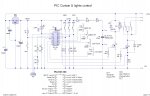
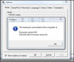
When I connect the attached to the PC and try to download to it I receive an error saying hardware not found.

I checked / tested the voltage at the serial pins as per view/options/serial port/test and it seems to be correct.

I have tried another PIC, and the supply voltages are OK .

have I done something silly or missed the obvious ....code attached for reference only....it didn't get that far !

Thanks in anticipation
 

Attachments

Dippy

Moderator
Well, I haven't been through your circuit with any degree of fine-toothed-combness, but a few qu's.

1. Have you tried downloading with peripherals removed. i.e. tested it simple?
2. Are you sure Tx and Rx haven't got reversed and are physically on the correct pins?
3. Is all this on hairy breadboard, stripboard(aka verobaord) or beautifully constructed pcb?
4. Have you checked power supply at the chip's pins (or legs as some people call them).
5. Your connector: Is it the same as Rev-Ed use? With the exact same pinouts? If so, you have it wrong. Assuming your pcb artwork/footprint is the same - which obv I can't see from here.

Comment: As a slight aside, is the 3.2V to remote critical? i.e. does it have to be really accurate?

Assuming the chip is OK your assumption will be correct - you have done something silly or missed something obvious. None of us can check to see if your layout fits your schematic (which I haven't studied in detail).
 

davidwf

Senior Member
haven't tested it bare....yet....but I can't see anything that would cause problems
tx & rx are correct...I think
it is contructed on a proper pcb
power at pins is correct
connector is not that one - it is too big, I used this one (have used it before on my coolbox controller project)

www.rapidonline.com item code 20-0144

http://www.rapidonline.com/Cables-Connectors/Connectors-Audio-Video/Jack/3.5mm-Miniature-stereo-PCB-jack-socket/63493/kw/3.5mm connector

connections are Tip=0V, ring = serial in, sleeve = serial out

3.2 V isn't critical but the stand alone remote that I am using runs on 3V so that was the easiest method I could devise to power it......and at this point it is not connected.

I will post the PCB design later, it's not available on this PC

Thanks
Dave F
 
Last edited:

BeanieBots

Moderator
The circuit should work if built as drawn.
I can only repeat Dippy's words but add one more thing to check.
Make sure that RESET is high. (check it at the pin).
 

moxhamj

New Member
Dippy almost certainly has hit the nail on the head (he owns a xtal ball!) but, can you please measure the volts at the point where the 10k and 22k resistor join, and with the PC connected. Do you get 0V, -5V, -12V or something else?
 

Mycroft2152

Senior Member
Also, shouldn't the reset be using a 4k7 resistor? As far as I could see you're using 1k aren't ya?
The 1k resistor is OK. Its purpose is to hold the reset high and limit the current when switched to ground.

Follow Dipy's advice and you should get a better understanding of the issue.

Myc
 

hippy

Ex-Staff (retired)
Staff member
Was the other PICAXE you tested put in this board when being tested ? If so then it suggests the 18X has been damaged. You can also try replacing the working PICAXE with the 18X on the working board.

If they aren't both 18-pin PICAXE's it's really only telling us that the serial cable works and the other board is wired correctly, nothing much about this board.
 

moxhamj

New Member
As a collective group we can all fix this (and have done many times before) but we need more information. Can you perhaps start with Dippy's questions. And also can you take a digital photo of the setup please? Many times the photo has revealed that a connection is not the same as on a schematic. We are all keen to get this working as the 18X is a great chip.
 

davidwf

Senior Member
FIXED !

:) :) :)

I looked into this again tonight and confirmed that the connections ARE correct, the voltage DOES switch as it should on serial input pin when in test mode, the supply voltage is correct and the PCB is correct....I then connected the download lead to a known working test board (thankfully this was not my first project) ....... and nothing !

I then re-installed the PICAXE program.....nothing......followed finally - and in somewhat desperation - I re-installed(USB) drivers ....and it worked first time.

A moral here perhaps....just because the pin voltage changes under test conditions and everything looks and tests OK don't assume (like I did) that the download circuitry must be working properly, clearly something had gone awry between the PIC program and Windows drivers.

Thanks to all for your prompt replies and suggestions, hopefully one day I will be able to offer help as well !!!

Dave Faulkner :)
 
Top