PC board fabs

julianE

Senior Member
The 3D prints came in, very fast shipping and I chose one of the cheap options. Both prints were for a nextion front panel, the 2.4 inch opening is tad too small, not my design, i can sand it down to fit and next one I'll do better. The photo is of 3.5 inch and is perfect. Sorry for the scratches on the nextion panel, it still has the protective film.
Quality of the prints far exceeded my expectation, very smooth high quality plastic. Total time from order to door, 2 weeks, not bad at all.

25658
 

Hemi345

Senior Member
@julianE Looks good. Did you get to pick the plastic they printed it in? PLA, PETG, ABS?
You mentioned you have a shop full of tools... I think that's what I like about our 3D printer the most is the ability to print jigs to use all tools I have. For example, if I need to install handles on some new cabinets, create a jig that has the different handle spacings and fits on the corner of the door so hole is drilled perfectly where I want it every time. Or create a jig to make a cutout that the Dremel tool can follow with a router bit installed.
 

julianE

Senior Member
create a jig to make a cutout that the Dremel tool can follow with a router bit installed
I too would like to make a jig for the dremel to cut out panel holes in acrylic.

This time around I chose SLA(Resin), 8000 Resin. There are many options of plastic to chose from, as far as colors it varies depending on material, seems like white is the most common choice.
 

oracacle

Senior Member
It's funny you mention his. We needed his for holding a work piece on a CMM in short order. Had it designed, printed and in use in less than 18 hours. The tool room would have taken a couple of weeks to make the same thing. And it cost less than £5 to produce including the electric to run the printer, better than a third of an hour's wage for a tool maker.
 

hippy

Ex-Staff (retired)
Staff member
if I need to install handles on some new cabinets, create a jig that has the different handle spacings and fits on the corner of the door so hole is drilled perfectly where I want it every time.
Kids and their new-fangled gubbins, eh? In my day we ripped the backs off notepads, crafted our own templates out of folded cardboard and sticky-tape, punched drilling marks with a compass or hammered a nail through. Tuppence ha'ppeny, done in minutes, and the only inconvenience being slicing through one's fingers with a scalpel or craft knife in the process.

Not really knocking it of course and would likely do the same myself these days if I had access to a printer. And there are times where one would be the perfect solution to my needs.

I picked up a few 'mains energy meters' dirt-cheap. They are plug-in and pass-through, unfortunately with non-UK plug and sockets. Easy enough to convert to plug and socket on flying leads but a pain to blank off the huge holes where the plug and socket were beyond just gluing a flat piece of plastic behind them. Not pretty. It would be so much easier to just print a domed filler than try to find something to fit or to bash into shape.
 

rq3

Senior Member
The 3D prints came in, very fast shipping and I chose one of the cheap options. Both prints were for a nextion front panel, the 2.4 inch opening is tad too small, not my design, i can sand it down to fit and next one I'll do better. The photo is of 3.5 inch and is perfect. Sorry for the scratches on the nextion panel, it still has the protective film.
Quality of the prints far exceeded my expectation, very smooth high quality plastic. Total time from order to door, 2 weeks, not bad at all.

View attachment 25658
I had a part 3D printed in 316 stainless steel by JLCBCB, using the same STEP file I had used to fabricate the same part using CNC machining by hubs.com.

The printed part got here much faster than expected, and looked great. BUT. The tolerances in the important axes were way off (I'm chasing microns), and the material was an absolute bear to machine. The part spent three days in hot alum solution to dissolve the drill bit I broke off.

I've never machined anything like this stuff, and I've machined a lot of weird material. It's absolutely, unequivocably, nasty. The CNC'd 7075-T6 unit is on the left, and the post machined 3D printed 316 stainless unit is on the right.

This is actually a part for a 3D printer. They have their place, but this isn't it.
 

Attachments

oracacle

Senior Member
Why are you chasing microns? At work we manufacture done aircraft parts and they are only going down to a few tens of microns. The parts are measured with a CNC CMM with a 7 micron tolerance. It of all the posts we make the toughest tolerance we measure in metrology is nomimal give it take 15 microns.
 

rq3

Senior Member
Why are you chasing microns? At work we manufacture done aircraft parts and they are only going down to a few tens of microns. The parts are measured with a CNC CMM with a 7 micron tolerance. It of all the posts we make the toughest tolerance we measure in metrology is nomimal give it take 15 microns.
Basically, because it's part of the fascination. My go-to printer is a delta design, currently with 5 micron resolution for each axis. Even the ambient temperature is important.
 

oracacle

Senior Member
So how are measuring that? Is the entire room temperature controlled? How long are leaving the material to acclimatise? Are you taking into account the temperature coefficient of the material that the object is made of, and there material of the measuring device. How are you calibrating the measuring device?

The CMM I use most is about £150,000 and only has a rated accuracy of 7 microns. Even when it's in a temperature controlled room. we tend to refer to medium tolerance is sub 50 microns (25 either side). As a result in curious as to how are actually getting your micron measurement and how repeatably you can measure to that level. How do you go about jigs and fixing for that repeatability, and how rightly is the temperature controlled. And how long are there materials being left to get the the temperature of the room.

I don't know how the slightly porous material of a material 3d print will effect the temperature coefficient of the steel either. Iirc steel is about 1.1 to the -6. So around is around 5.5 microns over 100 degrees.
And laser sintering runs around 250.

I literally measure stuff for a l living.
Just the other day I had 32,000 parts scrapped for being 9 microns over Max. Or 109 microns over nominal. I scrapped more than a dozen parts for being more than 30 microns away from nominal. I nearly had to scrap another part for having a surface roughness around the three micrometers. Aiming for 0.

You can most likely understand my skepticism about the accuracy of micron measurement claim in home workshops.
 

rq3

Senior Member
So how are measuring that? Is the entire room temperature controlled? How long are leaving the material to acclimatise? Are you taking into account the temperature coefficient of the material that the object is made of, and there material of the measuring device. How are you calibrating the measuring device?

The CMM I use most is about £150,000 and only has a rated accuracy of 7 microns. Even when it's in a temperature controlled room. we tend to refer to medium tolerance is sub 50 microns (25 either side). As a result in curious as to how are actually getting your micron measurement and how repeatably you can measure to that level. How do you go about jigs and fixing for that repeatability, and how rightly is the temperature controlled. And how long are there materials being left to get the the temperature of the room.

I don't know how the slightly porous material of a material 3d print will effect the temperature coefficient of the steel either. Iirc steel is about 1.1 to the -6. So around is around 5.5 microns over 100 degrees.
And laser sintering runs around 250.

I literally measure stuff for a l living.
Just the other day I had 32,000 parts scrapped for being 9 microns over Max. Or 109 microns over nominal. I scrapped more than a dozen parts for being more than 30 microns away from nominal. I nearly had to scrap another part for having a surface roughness around the three micrometers. Aiming for 0.

You can most likely understand my skepticism about the accuracy of micron measurement claim in home workshops.
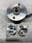
The original intent of my post was to point out that a part 3D printed out of 316 stainless steel may not meet expectations, and is a really nasty thing to post machine. But the experiment was well worth the price ($11 including shipping) from JLCPCB, who apparently do a very good job with printed circuit boards. I'm certainly not complaining about the 3D printed part, it just had characteristics that surprised me.

My 3D printer is in my cellar, which is 8 feet underground and has field stone walls and a concrete floor, both of which are well over a foot thick. The temperature remains constant within 0.1C for days at a time, and the printer and it's printing material live there so that they are pretty well stabilized.

The best I can measure directly is with a digital caliper, with 50 micron resolution. I can't speak to the accuracy of that resolution, but it is repeatable.

And if I am careful, and print an object 5mm thick, consisting of 1000 layers of 5 microns each, it will measure 5mm +/- 0.05mm. So each layer is pretty darn close to the 5 microns I calculate based on the stepper motors, pulleys, and belts. A small (say 2cm diameter) part also takes about 20 hours, so its not something I do very often.
 

oracacle

Senior Member
So it's a calculated value and bit directly measured.
They picaxe macros rail i built had a calculated resolution of 30 micrometers. I can't measure that.
 

lbenson

Senior Member
Thanks for posting your results, good to know i can get metal parts 3d printed.
Double plus. A piece on a brace I wear has worn. If I take the brace to where I can get it fixed, it's 4 hours of driving twice, separated by about a month when it would just sit in their shop. If I can get an aluminum replacement made, I can fit it myself. In fact, maybe I can repair a 20-year old replacement brace which is broken. I may have to take a class in exact measurement.
 

oracacle

Senior Member
I would suggest that you could get the measurements you need with a Vernier caliper but c couldn't say without seeing it.

If you can do the designs I suspect that someone can do a plastic test print to ensure that the measurements are correct before ordering the real thing.
 

papaof2

Senior Member
Double plus. A piece on a brace I wear has worn. If I take the brace to where I can get it fixed, it's 4 hours of driving twice, separated by about a month when it would just sit in their shop. If I can get an aluminum replacement made, I can fit it myself. In fact, maybe I can repair a 20-year old replacement brace which is broken. I may have to take a class in exact measurement.
You might have difficulty determining the radius of the curves on the edges of the piece or where there are holes, but it's relatively easy to remove sharp corners from aluminum with a file or coarse sandpaper. The length, width, thickness, hole sizes and distances between holes or between a hole and the edges of the piece should be somewhat simpler, although holes related to movable joints may have worn larger over time and the pivot points of those joints may have worn smaller.

If you could get a plastic prototype printed, you would know how close your measurements were the first time and be able to make any needed adjustments.
 
Last edited:

lbenson

Senior Member
Thanks for the responses. The radius of the curve is not critical--I think the only critical part is the location of the center hole. But I have enough experience with minor milling of aluminum (hand file, drill press) that I can probably deal with any problems--maybe not even drill it until I have it in hand and can use the enclosing piece to center it. If someone's quote of $7 for a piece of stainless steel (of unspecified size) is accurate, then I can afford retries.
 

julianE

Senior Member
If someone's quote of $7 for a piece of stainless steel (of unspecified size) is accurate, then I can afford retries
I have noticed prices make quantum jumps once you cross thresholds, with pc boards it's once you get beyond 100mm, even a couple mm over and price jumps. I was gonna print an entire enclosure in plastic but it would end up $20 for a simple box, much easier to have the panel printed and make the rest of the box out of plexi or other materials. i haven't made any metal prints but i can see making small parts to repair a CD player.
 

Hooter

Senior Member
I have used EasyEDA for PCB design, JLCPCB to fabricate the boards and LSCS for parts supply.
Never had an issue and they are all under the same roof - so to speak.
 

Hemi345

Senior Member
Thanks for the responses. The radius of the curve is not critical--I think the only critical part is the location of the center hole. But I have enough experience with minor milling of aluminum (hand file, drill press) that I can probably deal with any problems--maybe not even drill it until I have it in hand and can use the enclosing piece to center it. If someone's quote of $7 for a piece of stainless steel (of unspecified size) is accurate, then I can afford retries.
I don't have any idea what the part looks like, but if you can scan it in, you may be able to make a 3D model of it so it's somewhat dimensionally accurate. Like in this video:
(35) Scan to 3D Print using a Paper Scanner - YouTube

My daughter got some cat-shaped Post-It notes that she wanted a little dispenser for, so I used that technique above to get the shape and extruded it into a little holder for them and added a little cubby for some colored paperclips:

25681
 

lbenson

Senior Member
Hemi--thanks for that link--suggests a number of paths to follow. I can't quite do that scanning bit because the piece (maybe 4 inches long), is not broken off, but worn and part of the much larger brace. I'll find a way. I have never done anything 3D (except for a boathouse design back when the google tool was free), so it will be quite a learning experience.
 

julianE

Senior Member
A diptrace question. Have been making pc boards with transistors and I find that diptrace spacing of transistor pads is very tight, difficult to solder.
I'm tempted to use a 3 hdr model instead of a 3 lead transistor. It looks like the models can be edited, have not tried that yet. Curious as how others get around the very close spacing. I also notice that dip trace default pads for IC's are generally smaller than the usual commercial pc boards. as always any insight is appreciated. I seldom go more than 2 weeks without ordering a board, hopefully the low pricing and excellent service continues.
 
Top