New to the Forum

GBlair

Member
Hi Folks
New here and just getting my feet wet with the Picaxe. I have made me a proto board to play with and try and learn a few things using the Picaxe chips. What I want to do is monitor some solar projects that I am also working on (voltage and temperature and hopefully RPM). What would be a good temperature sensor to use that is readily available? I have some photos on my website http://www.projectgm.com/html/picaxe.html and will try and keep it updated as I progress with these projects. Any information on data logging will be helpful as well. I will be using the Picaxe-08M.

Thanks and enjoying the forum
Gerald
 

manuka

Senior Member
Welcome! We're a friendly lot but appreciate details, code & pictures when tricky Q's arise.

Although more costly than a thermistor,the inbuilt "READTEMP" command on a baby PICAXE-08M means that the DS18B20 is the temp. sensor of choice. Basic data logging with these is a proverbial piece of cake! See many resources => www.picaxe.orconhosting.net.nz
 
Last edited:

kevrus

New Member
I second that. Ive used the DS18B20 on a few occasions and found them superb. Getting negative temp readings using 2s compiment is a bit more tricky, but theres the challenge...have to say that I failed and got excellent assistance from this forum
 

hippy

Ex-Staff (retired)
Welcome to the forum and some nice boards there. I'd also recommend the DS18B20. More expensive but far easier to use than analogue sensors and no messing about getting them calibrated.

The only downside is the near 1 second time it takes to do a temperature sample and return a result but that can be worked round in various ways and often isn't a problem to start with.
 

BeanieBots

Moderator
I'd also suggest the DS18B20.
Hippy has pointed out the 750mS conversion time. However, you state that in the future you want to do data logging.
If that is the case, you will soon find the 08M limited on space to store data. At some point (after you have exhausted the 08M first) you will need to step to a device which can support external memory for logging data. When you are ready to do that, the 28X1 supports commands which can talk directly to the DS18B20 and does not need to wait for the conversion. Hence, the DS18B20 is an even better choice if you think about longer term.
One step at a time though. Stick with the well chosen 08M for now.
 

premelec

Senior Member
Is Jeremy still working with electronics? I miss his posts which were indicative of an active interest in a variety of subjects...
 

GBlair

Member
Thanks for the advice on the DS18B20 I will pick up a few and do look forward to working with some of the other Picaxe in the future.

I did receive the 08M’s today and have not tried them with my programmer that I built. I left it at work. I did try to bread board a couple up and can not seem to get them to work. They seem to take the code and I did just use the simple code of

Main: high 4
pause 1000
low 4
pause1000
goto main

I used the resistors and led’s that the manual said to use and did make a cable per the manual pin out. Follow the directions but they will not flash. Is there something that I am missing? Like I said I am new to this and really don’t know what I am doing. Any advice will be deeply appreciated. The Picaxe seem like something I really want to spend some time and learn. So many project that they could be used for.
Thanks
Gerald
 

Attachments

westaust55

Moderator
As Manuka said:
Welcome! We're a friendly lot but appreciate details, code & pictures when tricky Q's arise.
Hippy could well be right but a photo may help us identify the problem much faster then 20 questions.

In the meantime, not knowing your electronics experience, and since there is a bit of a lack of details on physical arrnagement of LED's atatched is a diagram showing how to identify the anode and cathode for an LED.
Yes, manual 1 page 53 shows an LED with "+" lead marked, but does not specifically state this must be to the positive side of the circuit/connections. Manual 3 on page 8 does not include the "+" indication against the LED arrangement diagram.

If not already cut, the longer lead is the anode and must go to the more positive side of a circuit, that is closest to the +5V / Vdd conenction.

Otherwise you will find a flat edge near the base of the LED on the cathode side. This flat face /cathode lead is to the negavite 0V /Vss conenction in the circuit.
 

Attachments

Last edited:

Texy

Senior Member
Looking at your website, you've already built the pcb, even before
your picaxe chip arrived:eek:
Very brave of you, LOL :D

Texy
 

GBlair

Member
Thanks again for all of the help. I thought maybe in all of the excitement I installed the LED in wrong but checked that. And yes I built the board before the Picaxe arrived but again was excited and wanted to hit the ground running. I will just take a step back do some more reading and double check what I have. I might (probably) have just done something wrong it would not be the first time. The board is at work so I might be able to mess with it today at lunch. I will let you know what happens and hopefully it will be successful.
Thanks again
 

eclectic

Moderator
Thanks Gerald.
First off, I'm assuming that the Picaxe has loaded correctly, if you
haven't reported any error messages.

Just a couple of questions.
1. I'm confused. Does your diagram show

metal legs/terminals 0 - 8 on the outside, and
Picaxe connections inside. (V+, gnd, serin, pins 0-4) on the inside?

2. Does the wire to the LED connect to

leg 3 pin 4 or
leg 4 pin 3?

e.
 

Attachments

GBlair

Member
eclectic
The diagram is leg 4 pin 3 and that is might have been my problem. I was programming pin 4 and testing leg 4 which is pin 3. The programmer that I built is working great and the LED's are blinking liek crazy so now I can play. Next I want to try some voltage measurements.

marcos.placona
I am using Eagle cad software. They have a free version that for me, right now works great. (http://www.cadsoft.de/)

Thanks
Gerald
 

eclectic

Moderator
Gerald
Some more references

1. Enhanced download circuit. See Manual 1. Page 32

2. Also very important are the capacitors, which are always
present on all the Picaxe protoboards.

See, for example post #3 in this thread.
http://www.picaxeforum.co.uk/showthread.php?t=8031&highlight=100nf+close

3. Picaxes with fixed inputs, such as the 08M, need to have all unused inputs
tied to ground, or to V+, using say 10k resistors.
There are many references on the Forum.
 

hippy

Ex-Staff (retired)
Re 3 : "Need to have all unused inputs tied ..."

Recommended and necessary in some cases but certainly not all. In almost none of my home projects have I bothered to do that.
 

Mycroft2152

Senior Member
BGblair used EAGLE to draw the board.

Then used EAGLE3D (a separate program) to create the photorealistic images.

EAGLE3D requires POV-ray rendering software.

It's a bit of a learning curve.

Myc
 
Last edited:

GBlair

Member
You are correct on the software. Once it is all set up works real well.

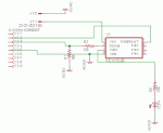
I have added the schematic for the proto board that I have working. http://www.projectgm.com/html/picaxe.html I did put in part of the enhanced serial download circuit. I did not put in the Shottky diode and I do have a place where I can add 2 additional Caps to the power circuit. I just did not have them on hand and while testing that part of the circuit it did seem like I was getting a clean and steady voltage. You don’t know how much I appreciate all of the help I have been getting and look forward to new projects. Hopefully I will be as beneficial to others as all of you have been to me. I did just purchase 10 of the DS18B20 as suggested.
Thanks
Gerald
 
Top