Hi all,
I've just got hold of a picaxe developers board with which to test and program some chips. I've written a couple of simple programs in the software and in the simulator they work perfectly, just as I want them to.
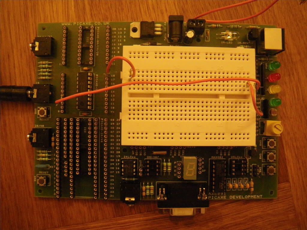
I'm currently just using a switch and two leds to test out some functions. I then send the program to the 18x chip and it says downloaded successfuly. I've wired up the chip to the leds and sw1 (I think) and all that happens when I press sw1 is the led lights, for as long as I press the button (in this case it should flash).
I'm sure its because I've put the jumpers in wrong but I can't find any sort of guide or instructions to learn from... Does such a thing exist?
Nick
I've just got hold of a picaxe developers board with which to test and program some chips. I've written a couple of simple programs in the software and in the simulator they work perfectly, just as I want them to.
I'm currently just using a switch and two leds to test out some functions. I then send the program to the 18x chip and it says downloaded successfuly. I've wired up the chip to the leds and sw1 (I think) and all that happens when I press sw1 is the led lights, for as long as I press the button (in this case it should flash).
I'm sure its because I've put the jumpers in wrong but I can't find any sort of guide or instructions to learn from... Does such a thing exist?
Nick
")