Multiple output switch from momentary input.

Shafto

Senior Member
Building another LED driver for a flashlight that I made. Right now It's using one of these drivers:

http://www.kaidomain.com/ProductDetails.aspx?ProductId=1801

3 AMC7135 chips, which are 350mA linear constant current regulators, and a control chip of some kind, I'm not exactly sure how it works, but the output isn't constant, I'd like to build a proper buck-boost driver for single cell Li-Ion input (2.7-4.2V).

I Have a couple of these chips: http://www.linear.com/pc/downloadDocument.do?navId=H0,C1,C1003,C1042,C1116,P15693,D10838

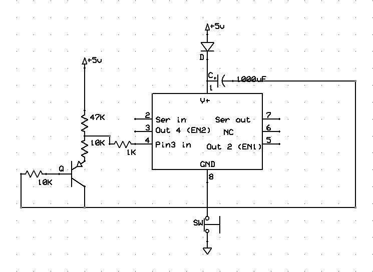
There are 2 enable pins that ground through 2 different current setting resistors. So you can have 3 light levels by energizing EN1, EN2, or both, and when both are grounded, no current is drawn.

Now I'm wondering how best I can utilize a momentary push button switch to cycle 2 outputs.

low, low
high, low
low, high
high, high

I was thinking of maybe using a SOIC 08M for the job, but how low of a voltage will one of these chips work to? Also how low can I possibly get the current draw? I'd like to keep the driver as efficient as possible.

Maybe there's some other more simple chip that could do the same job much more easily, but I don't really know what to even start looking for. I have some other LED drivers that I'd like to utilize adjustable output with.. grounding the LEDs through different Rsns resistors using FETs or something similar.. but these drivers are higher voltages, one of them up to 25V, so I suppose it wouldn't be too out of the question to use a small linear regulator to power a picaxe, but other drivers I have that are 50V would require a switching voltage supply for the picaxe I imagine.. since I need to keep things as small as possible, and simplicity is always good. Suggest away please!

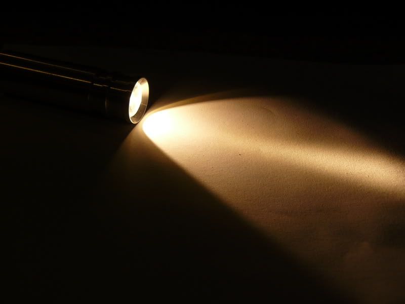
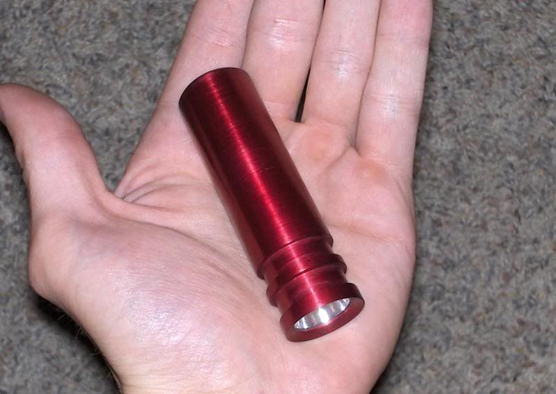
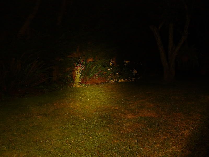
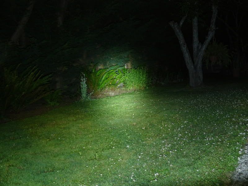
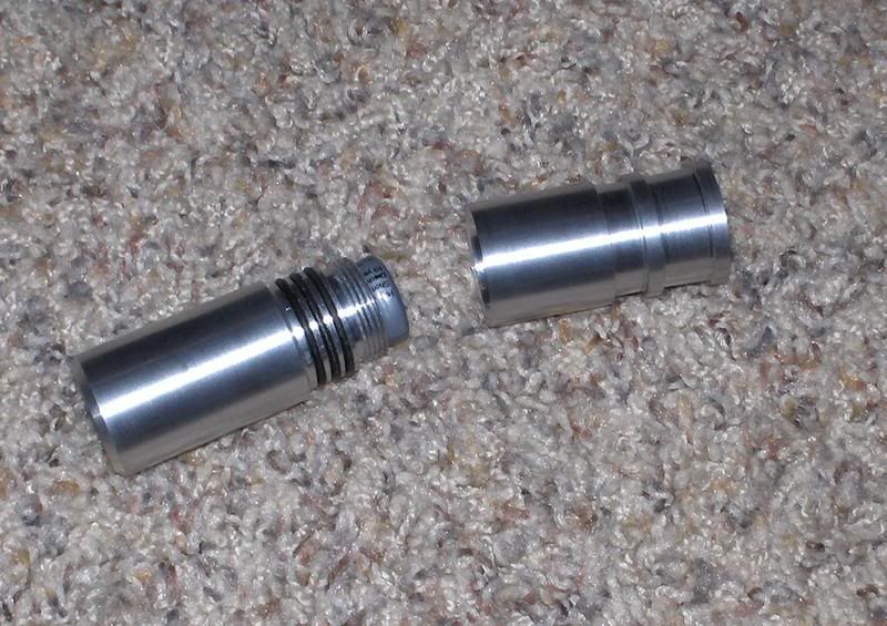
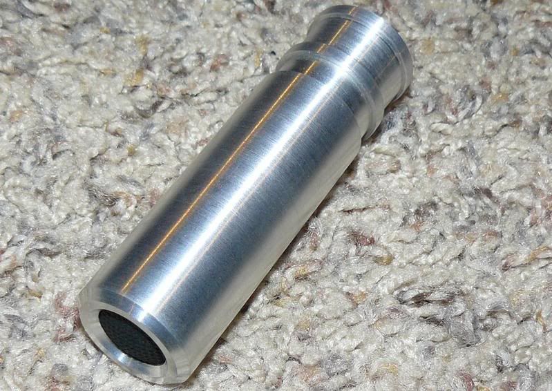
And I always like to put some pics in my threads, so here's a couple of the flashlights I turned on my lathe, I also set up an anodizing tank.. these use high power CREE LEDs, one of them a warm white LED around ~2800K, very warm, the other is a ~5000K LED. Warmer LEDs have lower flux, but that one is extremely warm, I have some nice 3500K LEDs with a nice compromise between colour and flux.


BCJKiwi

Senior Member
1 Input for the button,
1 Output to drive each of the EN pins.

Presumably the idea is to have a single button that steps through the four options.

The BUTTON command could be used which would give debounce control and repeat if that was required.

The logic could be to increment a variable from 1 to 4 on each button press and back to 1 again.

Then the two EN outputs could be switched between high and low to produce the four options.

e.g. some pseudo code;
Code:
SYMBOL EN_1 = 1   'Torch
SYMBOL EN_2 = 2   'Flash
 
If     b0 = 1 then low  EN_1,      EN_2
ElseIf b0 = 2 then low  EN_1, High EN_2
ElseIf b0 = 3 then High EN_1, Low  EN_2
Else               High EN_1,      EN_2
EndIf
Of course you'd probably want to use a better construct like Branch instead of If

08M is supposed to be able to run down at 2V @4MHz and 3V @8MHz. So the 2.7 to 4.2 range should be OK
 

Shafto

Senior Member
The switch right now is a click on-off switch that engages in a reverse style, it comes on once the button clicks and is let all the way out, pushing it in slightly without clicking it fully will momentarily turn it off, and this is how the light level is changed with the current driver.. by momentarily killing power to the driver.

Since the ground runs through the body of the flashlight, the driver has to be at the top, so I have to use the same type of switching action to trigger the micro controller at the top, so maybe have a capacitor that could keep the picaxe going for just a fraction of a second, and detect the ground interrupt to switch the outputs.

Using a clicking switch like I currently do to switch power to the unit off completely works, but it would be even better if I could go to a full momentary switch, since they last much longer. If I could have the picaxe enter a sleep mode and only wake up on inputs, that would be great, but taking a look through the commands I'm not too sure how to achieve that, or if it's possible.
 

BCJKiwi

Senior Member
Don't quite follow but if I have the gist of it correct, the switch is actually a momentary break. If so, the button command is still your friend as it can be configured for the switch either way, make or break.

Sleep and waking up from it have all been covered a number of times before. But for a torch one would have thought you would want to power everything off completely between uses, not just go to low power modes.
 

Shafto

Senior Member
Sounds like you've got it figured. A momentary break in the ground to switch the outputs, but I figure I'll need a capacitor to supply power for that momentary break to the picaxe, with a schottky diode behind the cap so it can only drain into the picaxe?

How much power will a picaxe at 4mhz draw on average? or when it's asleep? The datahsheets don't seem to give you a ballpark of current draw.. as I might want to use the sleep/wake-up function all the time just so the picaxe isn't wasting power.. I really don't want to effect the efficiency of the driver much.

Killing the power completely with a clicking switch would be desirable if the picaxe draws much while asleep, but if it's a minuscule amount, then I think the advantage of using a completely momentary switch would come into play.. as they are much more reliable, and smaller.


Edit: I found a great thread here while searching: http://www.picaxeforum.co.uk/showthread.php?t=8353

I don't see why I can't just run the picaxe at 31kHz all the time? I don't think it will need a high speed just to monitor 1 input. If I can have the power draw down to 100uA, which looks pretty reasonable, I'd be happy with that. On a ~600mAh battery, it would take many months to drain.

Then a simple coding change of just adding another "mode" with both EN1 and EN2 off with a momentary switch, or if using a latching switch that can also be momentarily turned off by only pushing it in slightly (this is what is currently used) you could ditch the EN1 and EN2 off "mode" and just click the light off at the switch.

I've got a couple 08s here in DIP form, but they're not the M version, I hope I can still turn off the ADC, underclock, and turn off the brownout with these older 08s? Gonna start rigging up the breadboard and find out I suppose.. I've never poked anything before, I'm glad these are cheap.

Then if it all works out.. to find a supply of the 08Ms in SOIC form, HVW Tech here in Canada doesn't have the SOIC 08s, but I imagine they could probably get some.
 
Last edited:

Shafto

Senior Member
Far from figured, my coding skill is next to nill. The buttom command looks like more complication than I need, I think I'll just use a short pause to debouce?

I looked at the branch command but I don't really understand it. Why is it better? for now i'm just going to try and see if I can get it cycling through the inputs with a positive switch.. then I'll move on to breaking the ground and keeping the picaxe powered by a cap to try and achieve the same thing.

I'll be pretty happy with myself if I can figure out how to do what I want with "if" commands by the end of the night.
 

BCJKiwi

Senior Member
Figured, as in the logic of how to do it!

A short pause will work but won't give you an auto repeat.

Use the if..elseif..endif.
change to branch later if you want. Branch could be considered as a different way to write the if..elseif..endif and can be easier to follow the way it is laid out. it also takes care of the syntax issues that can arise in with if....

As the system is a low change, low speed app, then the basics should work well.
 
Last edited:

Shafto

Senior Member
I imagine there's a better way to do it, but I got it working faster than I thought I would.

Here's what I did:

Code:
symbol EN1 = 2
symbol EN2 = 4

LowOut:

pause 125

high EN1
low EN2

if pin3 = 1 then goto MedOut

goto LowOut


MedOut:

pause 125

low EN1
high EN2

if pin3 = 1 then goto HighOut

goto MedOut


HighOut:

pause 125

high EN1
high EN2

if pin3 = 1 then goto LowOut

goto HighOut
Though this inherently has the repeat function that the button command has.. I would actually prefer that it didn't do this.

I imagine doing it the way you suggested would work better, but I don't know how to make a variable = anything other than 1 or 0 ? I guess there's got to be some way to set up a counter or something to just count the inputs on pin3 and and store that as a variable, but I don't really know how to do that yet.
 

BCJKiwi

Senior Member
Just read the input and add 1 to the variable each time it is high (or low ~ i.e. what you are checking for). Then when it gets to > the max value you want, make it the min value you want.

Untested suggestion only
Code:
b0 = 1   ' set b1 to 1 once at the beginning of the program
set EN to what you want here for power up
main:
If pin3 = 1 then
   b0 = b0 +1
   If b0 = 4 then
      b0 = 1
   EndIf
EndIf
 
If     b0 = 1 then low  EN_1,      EN_2
ElseIf b0 = 2 then low  EN_1, High EN_2
ElseIf b0 = 3 then High EN_1, Low  EN_2
Else               High EN_1,      EN_2
EndIf
goto main
or something similar to suit your needs
 
Last edited:

Shafto

Senior Member
Thanks BJK, I'l try that out soon.

Right now I'm working on the issue of switching. I'll draw up a wiring diagram here in a minute..

What I ended up doing what tying pin3 high, and then keeping it constantly switched low, when the switch is released from ground it goes high and the mode switches... all works well.

Then I moved onto my model with the capacitor, I used a 16V 1000uF I had around, seems to have plenty of power to keep things going, yet I can't get the modes to switch by releasing ground to the whole circuit.

I've kept the capacitor isolated from the ground input to the switch, and tied it high to the capacitor, so that when the ground is removed from the whole circuit, there should be no ground anymore on the switch, and it should go hi because it's tied hi after the cap that's still supplying power, but the mode won't switch.. kind of stuck now.. maybe setting up the diagram will give me an idea.


Edit: having trouble figuring out how I can utilize the capacitor to still supply +V and GND to the picaxe while the switch will lose it ground contact, pushing it high, since the tie up resistor is connected to the +V after the capacitor. I thought I had it all figured out, but now I can't seem to wrap my head around how to make the picaxe switch by momentarily interrupting the entire ground connection to trigger the switch, and somehow keeping the picaxe momentarily supplied with power to perform the switch.
 
Last edited:

Shafto

Senior Member
Well, I'm stuck.

Maybe my logic was flawed in thinking that I could kill the ground to the entire circuit and somehow still keep the picaxe powered to detect the switch. It just won't seem to work.

I'm using LED indicators to see what's going on with the outputs, and when I kill the ground, they slowly dim, and while there's no ground, I can then break the connection from pin3 to ground, (even though ground is disconnected, and the capacitor is isolated to only feed the picaxe with diodes in and out) and it will switch.. so there's enough power from the cap to do it, but somehow breaking the whole ground just isn't detected by the switch. Is my logic totally flawed here? maybe I can't isolate the ground potential like I'm thinking I can with a diode? (so the switch (pin3) won't see ground but the picaxe still will?)

Is there some known way to make the picaxe switch by momentarily removing it's ground? Or some configuration of components to do such a thing? I'm racking my brain, but I can't really come up with a solution visually in my head, not really sure what to do now.
 
Last edited:

hippy

Technical Support
Staff member
There are two possibilties I can think of ( easier to visualise as a +V switched line then translate for switched 0V operation ) ...

1) A separate small capacitor with a fast decay; that drops as the switch opens while the chip remains powered by the slower decay reservoir capacitor.

2) Monitor the current. Put the LED of an opto-isolator in-line with the battery ( +V or 0V ) and use the transistor on the reservoir capacitor powered side. As you probably cannot simply put a LED inline you may have to have the LED+R across +V and 0V and then isolate +V from PICAXE+cap with a blocking diode, thus LED is lit only from battery, not from the PICAXE cap.
 
Last edited:

BCJKiwi

Senior Member
How about a sketch of the circuit or a logic diagram of what you are trying to achieve. - a bit lost between the PICAXE, the fancy buck/boost with 4 states, and, what you want to keep running and what you are happy to shut down completely.
 

Shafto

Senior Member
I'l post a sketch now.. I just didn't because once I started sketching I got even more confused. Thanks for the suggestions hippy, I've actually figured it out now, through use of an PNP transistor, but somewhat by accident, and I can't really say I even understand how it works, but it's doing what I want!

I'm sure when I post the sketch someone will be able to explain what's going on.


Edit:

Alright, here it is, all working.


I suppose the tie up 47K resistor keeps the output high, even though the transistor is connecting it to ground? and then once ground is removed from the whole circuit, the tie up resistor loses power since it's before the cap, and then the transistor pulls the switch low, and it switches.. didn't mean to do it like that at all, but I'm happy it's working now.

I had this setup first of all to push pin3 high when the ground was lost, and thereby turning off the resistor, then I was going to place the 47K after the cap so pin3 would see +V and go high to switch. But then I accidentally attached the 47K before the cap, and when I tried the circuit it worked, but it reverse, it was switching all the time and stopping when I removed power, so I just reversed the switch of pin3 in the code.. and I ended up with my solution by total mistake! Neat I suppose, but I still don't understand how the 47K is overpowering the transistor to ground to keep the pin high... but oh well, as long as it's repeatable.
 
Last edited:

hippy

Technical Support
Staff member
My previous suggestions are more complicated than necessary. I think this should work, it does for sending data over a pair of power lines. It shouldn't matter whether the switch is in the +V or 0V rail.

Code:
                                .------.
+V ---O  O----.----|>|----.-----| +V   |
              |           |     |      |
              }-----------|-----| Ix   |
             .|.        __|__   |      |
             |_|        --.--   |      |
              |           |     |      |
0V -----------^-----------^-----| 0V   |
                                `------'
 

Shafto

Senior Member
I tried out the other code, it works too with a couple tweaks, but if pin3 is low as the micro makes another loop, it just switches again, so it does the same thing mine did. But that will be solved when I have the full setup going by matching the pause time to the time it takes for the cap to run out of power to keep the micro going.

I'm not too good with the ascii art, I can see the diode and the cap, is that other component in there a diode as well? If so it would seem that's the same as my setup, except I have a transistor where the diode is in yours. I tried the diode in place of the transistor, but it won't switch that way.

I still don't fully understand how it's working, how the 47K is keeping the pin high while the transistor has it tied to ground through a 10K (accidentally left 10K out of first schematic, updated now) After that I know what's going on, once ground is interrupted, it goes low because the 47K pull-up loses it's connection to +5 as the only current flow is now through the cap, which is isolated on the positive side, but the GND side of the cap, which isn't isolated, pulls pin3 low through the transistor and makes the switch.
 
Last edited:

Shafto

Senior Member
Ok! coming along nicely. Working on power consumption now. Using disablebod I've got the power consumption down to 50uA at 3.5V with no outputs active and all pins tied low at 4mHz. At 2.7V I'm getting 18uA, and 4.2V is about 90uA.

Now that's pretty good, but I don't understand why underclocking the chip makes it draw more power? This goes against everything I've been reading.

When I underclock the chip to 31kHz I get 55uA at 3.5V, 22uA at 2.7V, and 117uA at 4.2V

So what's going on, why is underclocking making me draw slightly more power?

Here's the code I'm using now, replacing the pause command with nap cut power draw in half.

Code:
symbol EN1 = 2
symbol EN2 = 4

disablebod
poke $1F,0               'disable ADC
poke $8F,%01100000 'set clock to 4mHz

pause 5

NoOut:

nap 3

low EN1
low EN2

if pin3 = 0 then goto HighOut

goto NoOut


HighOut:

nap 3

high EN1
high EN2

if pin3 = 0 then goto MedOut

goto HighOut


MedOut:

nap 3

low EN1
high EN2

if pin3 = 0 then goto LowOut

goto MedOut


LowOut:

nap 3

high EN1
low EN2

if pin3 = 0 then goto NoOut

goto LowOut
I tried a few different clock speeds, 8mHz is actually the lowest.. ? I'm boggled.. only lower than 4mHz by about 1uA though. But the lower I make the clock, the more power it consumes.
 
Last edited:
Top