MP3 player for 4 year old

nbw

Senior Member
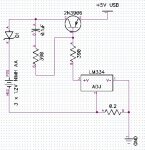
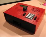
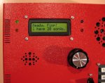
This is an MP3 player I built using a VMUSIC module. It has a 128Mb card which is enough for about 24 songs for my 4 year old son. It features a 16x2 LCD to display song titles, run time etc, as well as LEDs to indicate playing, low battery, unit turned on, and charging states. There's a headphone socket so he doesn't disturb the rest of the family, and an in-built 8 ohm speaker, with a simple amp unit to beef up the sound a little. And of course a volume control! It's run off 3 x AA 1.2 NiMH, with a step-up converter to get 5V. You can plug it into a USB port of a PC for charging (a simple charge-n-check circuit), as well as a plug-pack (USB is easiest). It features a keypad and easy to use menu so he can play an individual track, play all, stop, pause etc. He can also check a graphical voltmeter showing the amount of "juice" left in the player, and come see Dad when it's running low :)

He typically gets about 7-8 hours of music before it needs a recharge.
 

Attachments

hippy

Technical Support
Staff member
Your other two projects ( aquarium controller and coffee monitor ) have attracted some attention but this one has gone by with no comment, so I thought I'd just say I'm impressed.

I particularly like that you've got track names and other information. Is there any source code you're going to release ? And I'm sure people would also be interested in your circuit / software for charging via USB.
 

nbw

Senior Member
thanks! My code - shamefully - was not as clean nor efficient as it probably could have been, my excuse was I had a 3.5 year old nag-nag-nagging me to finish it. But, it works. It would have been nice to have the filenames etc in a txt file and to be able to read the time elapsed from the VMUSIC2, but I could never get mine to do this - not for lacking of trying. In the end I used the 1Hz blip from the AXE033 module as a second counter, and just let the picaxe do it.
For the former, I just put the file names in code at the start of the program. I used a 28X1 of course for the VMUSIC2, and with 4K of code I had a fair bit of left-over :)

I'll rummage around for the circuit for charging off USB. I know the best way is with temp sensing, however I went for a slightly simpler approach that actually cuts off when 4.26V is reached over the 3 NiMH AA cells. It means of course that the cells won't be charged as fully as they might be otherwise, but as Finn said "I just want it to play music Dad" LOL.

I'll see if I can find the circuit diagram... it was a little while ago but it'll be in the pile of sketches, bills and congratulations-you're-the-lucky-one-millionth-customer-don't-bin-this-envelopes.

cheers :)
 

nbw

Senior Member
p.s. now that Mycroft has introduced me to DIpTrace, I might even be able to convert it to a professional (and readable) diagram!
 

womai

Senior Member
The finish of the enclosure is impressive. Very professional and clean. What did you use to create those cutouts - the speaker holes seem to be slightly irregularly placed so I guess just a standard drill press, right? But how did you get the edges of the rectangular cutouts to be so straight and regular - do you own a mill? (I don't, and since my manual skills are average at best I always struggle to cut a perfectly straight line into an enclosure - at the latest when I insert the LCD display it shows that the display's edge is much straighter than my cut :eek:

Wolfgang
 
Last edited:

nbw

Senior Member
Yes, a standard drill dress. I should have done better with the spacing :) FOr the rectangular cut-outs, I draw the rectangle, drill a perimeter of holes a few mm on the inside of the shape, then dremel out the inside so most of the cut-out is removed in one piece. Then I use a fairly fine 1" wide file (and more patience than I thought I had!) to ever so slowly edge towards the rectangle, testing the LCD or other component when I think I'm getting close.

Round components are much easier!

Finn (4 year old) contributed by 1, saying he wanted a shiny knob for the volume control and 2, picking a bright red Ferrari paint can from the hardware store :)
 

nbw

Senior Member
Hi all, here's the basis of the very simple charging circuit, centred around an LM334. I know it's not temp-sensing which would would be best, but this is adequate for the mp3 player. This circuit limits the current to a constant value, about 180mA from memory. The diode is a low drop about 0.2V schottky - I can't remember the exact type - to ensure when the charging circuit is turned off you don't get back flow. Note that with 5V in from a USB port, and the 0.2V drop, there isn't much headroom for the 3 1.2V cells - about 1.5V when flat, and around 0.5V when charged. So it's not a fast charger.

Accompanying this, I had the 5V from the PC going into a voltage divider, and used that as a reference into a picaxe ADC port to gauge how charged the batteries were. I turned the charging off when the batteries reached 4.3V, as a safeguard, rather than trying to time etc (around 1.43V per cell). Using temp sensing, more could be squeezed out of the batteries, but this is a good enough charger.

If you wanted to charge faster, you'd need more than 5V input. You could step it up to say 7V, then your charging current becomes higher - around 290mA from memory.

The diagram was done in DipTrace, rename the extension to .dch

Any improvements on the circuit, please let me know.
 

Attachments

nbw

Senior Member
Hi Jeremy.

sure, here it is. It's been a while since I made this circuit and my memory is failing, so caveat emptor :) It still works fine in Finn's mp3 player ! I'm sure others can build on and improve it.
 

Attachments

Jeremy Leach

Senior Member
I've just browsed about USB currents, and just for info found:

To be compliant with USB Specifications (Rev. 1.1),
a high-power function must not draw more
than 500 mA from the bus during normal
operation.
There are additional current restraints on a
high-power USB function that apply during
system start-up or when a device is initially
connected to an active bus. Until a device is
properly configured by the USB system, the
device may not draw more than 100 mA from the bus.
 

nbw

Senior Member
That's the other consideration I looked at. While not too concerned about being fully USB compliant, I didn't want to nuke my computer either. I found that charging slowly, drawing less than 200mA worked fine, and Windows neither noticed nor moaned about an unrecognised device.
 

Jeremy Leach

Senior Member
That's good. I didn't know anything about the USB spec and how much current it could deliver, and even 180mA sounded a lot to me, so I looked it up ;)
 
Top