I've looked closely at the audio switching part of your circuit.
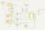
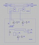
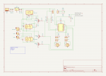
If I understand correctly, two mono signals enter at J2-1 and J2-3. The first relay selects one of the two and sends it to the second relay, which then outputs the selected signal to either J3-1 or J3-3.
( Is this correct, as your description mentions a single output with a 'mute' function, but it doesn't look like that ? )
Also, I can't see where the grounds for these four signals are. Are they the middle pins on J2 and J3 ?
If that is the case, and your drawing is accurate, then the audio ground does not look to be connected the control ground in any way. This is a very Good Thing !.
Do a continuity test between audio ground and control ground. There should be no connection at all.
If this is the case, then we can rule out ground bounce, and if there is noise on the 5v or 0v rail, this will not reach the audio directly, so must be getting in somewhere else.
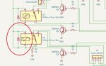
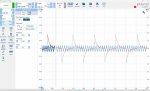
Some big suspects are the relays. If these are reed relays, then they are just a coil wrapped around a pair of contacts. These contacts are long compared to the coil, and in very close proximity to it. Any switching noise from the 5v will appear in the coil, even if the coil is off. This noise will induce further noise in the contacts. Even with no noise, there will be an induced signal when the relay is switched normally. You will always have a switching 'click'.
Even if you do manage to eliminate every source of switching noise, there is still a noise source beyond this circuit, i.e. your input signals !.
Imagine input A is at the top of a sine wave audio signal, and input B is at the bottom. If you then switch from A to B, or B to A, the amplifier will see a rapid change in level, which will sound like a click.
( This is why many audio routing devices use opamps or VCAs as selectors, so they can be ramped, which eliminates switching 'clicks' altogether. Another way of avoiding clicks is to mute the output, switch the relays, then unmute the output. If this is done with a soft-mute circuit then the results can be as good as an all solid state solution. )