raptorbasher
New Member
Hi Everyone,
I have completed my project to build a multi channel lighting timer/dimmer for a new marine aquarium that I hope to set up soon. The commercial items are quite expensive so I thought I would have a go myself.
I have three independant channels, with separate on and off trigger times, an adjustable fade time and a temperature display added for an accurate water temp.
I bought a second hand all in one tank that had been converted to LED lighting ( albeit in a crude fashion but there was no controller or timer...) so there is an 'aquabeam' tile that has 10 x 3 watt leds, ( 7 ultra white, 3 blue ) on channel 1, driven at 700mA. to help with even lighting I have added another 4 x 1 watt whites on channel 2 at 350mA and 4 x 1 watt blues on channel 3 also at 350mA. The third channel has a minimum level that leaves the moonlight shining at night.
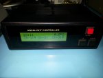
I am using a salvaged LCD 2 x 20 display, a picaxe sheild kit with 28x2 on board, the LCD serial module and a few LED drivers. I fitted the RTC and backup batt onthe protosheild that came in the kit. Fitted it in a maplin project box, milled out the front and back panels with my homebrew CNC mill. The power supply is a donated Dell laptop supply so it is a safe consumer grade item, with more than enough current for all LED's on full power at 19.5 volts. I have DC barrel connectors on the back for the channel outputs, 3.5mm jacks for programming the sheild and the LCD driver and a 3.5 mm jack for the remote temp sensor ( potted in a small test tube ) a small switched mode PSU module regulates the supply down to suit the picaxe bits. Finally I printed out a front panel using OHP films for inkjet and using two layers back to back its a deep black with text showing through. The LCD shines through and looks okay.
Here is the code if anyone is interested, probably a billion better ways to do it but it works and I really enjoyed the process!
Things I would like to improve or add...
Timing of button inputs...It works as is but could be better.
adjustment of moonlight level via menu ( ran out of variables )
a nice blue display!
animated characters always look nice to me so hell why not")
use the temp sensor to control the ventilation fan over the water...
Thanks for looking.
Tim
I have completed my project to build a multi channel lighting timer/dimmer for a new marine aquarium that I hope to set up soon. The commercial items are quite expensive so I thought I would have a go myself.
I have three independant channels, with separate on and off trigger times, an adjustable fade time and a temperature display added for an accurate water temp.
I bought a second hand all in one tank that had been converted to LED lighting ( albeit in a crude fashion but there was no controller or timer...) so there is an 'aquabeam' tile that has 10 x 3 watt leds, ( 7 ultra white, 3 blue ) on channel 1, driven at 700mA. to help with even lighting I have added another 4 x 1 watt whites on channel 2 at 350mA and 4 x 1 watt blues on channel 3 also at 350mA. The third channel has a minimum level that leaves the moonlight shining at night.
I am using a salvaged LCD 2 x 20 display, a picaxe sheild kit with 28x2 on board, the LCD serial module and a few LED drivers. I fitted the RTC and backup batt onthe protosheild that came in the kit. Fitted it in a maplin project box, milled out the front and back panels with my homebrew CNC mill. The power supply is a donated Dell laptop supply so it is a safe consumer grade item, with more than enough current for all LED's on full power at 19.5 volts. I have DC barrel connectors on the back for the channel outputs, 3.5mm jacks for programming the sheild and the LCD driver and a 3.5 mm jack for the remote temp sensor ( potted in a small test tube ) a small switched mode PSU module regulates the supply down to suit the picaxe bits. Finally I printed out a front panel using OHP films for inkjet and using two layers back to back its a deep black with text showing through. The LCD shines through and looks okay.
Here is the code if anyone is interested, probably a billion better ways to do it but it works and I really enjoyed the process!
Things I would like to improve or add...
Timing of button inputs...It works as is but could be better.
adjustment of moonlight level via menu ( ran out of variables )
a nice blue display!
animated characters always look nice to me so hell why not
use the temp sensor to control the ventilation fan over the water...
Thanks for looking.
Tim
Attachments
-
15.1 KB Views: 104
-
 306.3 KB Views: 126