LCD Contrast

George Sephton

Senior Member
Hi,
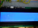
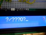
Im using the common LCD screen with the Hitachi chip with it, this one is blue and if you type lcd screen into ebay one of the first 100 results are my one. Its quite a common one but its got a weird contrast. I doesn't have a clear white text display like in the pictures but is quite faint and I don't know why. Im follow hippy's 2-wire lcd interfacing tutorial but the contrast is very low. However if I remove the LCD screen and start the power then add it, firstly the lcd screen hasn't been initisalised and a crystal white clear ? appears and I cant work out why. Im using the 74HC164 chip with a PICAXE 08m. Ive attached the 2 different screens to illustrate what i mean.
Thanks,
George S.
 

Attachments

westaust55

Moderator
CAn you provide a link to the LCD module you have.
Just saying it is on Ebay is no help - is is Aust, UK, US or other Ebay site?

Most have a potentiometer for contrast control. Does this one have software control like some mobile phone LCD displays I have experimented with.

Can you upload your code.
Do you have a say 500ms or even a 1sec delay before sending a command to the LCD module.
 

George Sephton

Senior Member
Oh sorry, its ebay UK: http://cgi.ebay.co.uk/ws/eBayISAPI.dll?ViewItem&item=260334150030&ssPageName=ADME:B:EOIBSA:UK:11
does that work?

There is a potentiometer and everything i know about that. Its 10K and is either invisible or just faint as in the picture. I tried a 100K but no difference.

Here's my code:

Code:
SYMBOL DAT = 1 ; Pin number of DAT line
SYMBOL CLK = 0 ; Pin number of CLK line
SYMBOL DAT_PIN = pin1 ; Pin number of DAT line

SYMBOL CLK_PULSE_LENGTH = 1 ; 10uS
SYMBOL E_PULSE_LENGTH = 1 ; 10uS

SYMBOL RSCMDmask = %00000000 ; Select Command register
SYMBOL RSDATmask = %00001000 ; Select Data register

SYMBOL countertop = b0
SYMBOL counterbottom = b1
SYMBOL get = b9
SYMBOL outbyte = b10
SYMBOL dataOut = b11
SYMBOL bitNumber = b12
SYMBOL rsbit = b13

PowerOnReset:

GOSUB InitialiseLcd
Goto Main

Main:
    gosub ClearScreen
    data 70,("Top Line")
    data 87,("Bottom Line")
    gosub WriteToTop
    gosub WriteToBottom
    goto Main

ClearScreen:
    pulsout CLR,10
    return

WriteToTop:
    outbyte = $80
    gosub SendCmdByte
    
    for b2 = 70 to 86
        read b2,outbyte
        gosub SendDataByte
    next b2
    return

WriteToBottom:
    outbyte = $C0
    gosub SendCmdByte
    
    for b3 = 87 to 127
        read b3,outbyte
        gosub SendDataByte
    next b3
    return
    
InitialiseLcd:

FOR get = 0 TO 5
READ get,outbyte
GOSUB SendInitCmdByte
NEXT

' Nibble commands - To initialise 4-bit mode

EEPROM 0,( $33 ) ; %001?---- %001L---- Display Format
EEPROM 1,( $32 )

' Byte commands - To configure the LCD

EEPROM 2,( $28 ) ; %00101000 %001LNF00 Display Format
EEPROM 3,( $0C ) ; %00001100 %00001DCB Display On
EEPROM 4,( $06 ) ; %00000110 %000001IS Cursor Move

; L : 0 = 4-bit Mode 1 = 8-bit Mode
; N : 0 = 1 Line 1 = 2 Lines
; F : 0 = 5x7 Pixels 1 = N/A
; D : 0 = Display Off 1 = Display On
; C : 0 = Cursor Off 1 = Cursor On
; B : 0 = Cursor Steady 1 = Cursor Flash
; I : 0 = Dec Cursor 1 = Inc Cursor
; S : 0 = Cursor Move 1 = Display Shift

EEPROM 5,( $01 ) ; Clear Screen

RETURN

SendInitCmdByte:

PAUSE 15 ; Delay 15mS

SendCmdByte:

rsbit = RSCMDmask ; Send to Command register

SendDataByte:

dataOut = outbyte & %11110000 | rsbit
GOSUB TransferTo74LS164
dataOut = outbyte * %00010000 | rsbit
GOSUB TransferTo74LS164

rsbit = RSDATmask ; Send to Data register next

RETURN

TransferTo74LS164:

LOW DAT ; Clear 74LS164
FOR bitNumber = 0 TO 7
PULSOUT CLK,CLK_PULSE_LENGTH
NEXT

HIGH DAT ; Transfer data
PULSOUT CLK,CLK_PULSE_LENGTH
FOR bitNumber = 0 TO 6
DAT_PIN = dataOut / $80
PULSOUT CLK,CLK_PULSE_LENGTH
dataOut = dataOut * 2
NEXT

PULSOUT DAT,E_PULSE_LENGTH ; Pulse E

RETURN ; Completed transfer
Thanks
 

westaust55

Moderator
In your program, immediately after the referenced label (below) try adding the extra line
Code:
InitialiseLcd:
Pause 500     ; or even PAUSE 1000
Purpose is to give the LCD time to initialise. If you have a lot of capacitance on the supply lines, that can affect the time for the voltage to rise and cause problems in which case a longer period and may need to issue a reset command first.
 
Last edited:

hippy

Ex-Staff (retired)
Also, put a PAUSE before GOTO MAIN, or move GOSUB CLEARSCREEN to before MAIN:

You are repeatedly clearing and drawing the display so you are effectively PWMing the characters, they don't have the time to reach 'full brightness'.
 

George Sephton

Senior Member
Oh the clearscreen isn't used anymore because it didn't work, what pin would I have to connect it to to make it work, I had it connect to pin 8 of the 74hc164 but that didn't work is that right? Otherwise Ive added the pauses and still no luck :(
 

westaust55

Moderator
Oh the clearscreen isn't used anymore because it didn't work, what pin would I have to connect it to to make it work, I had it connect to pin 8 of the 74hc164 but that didn't work is that right? Otherwise Ive added the pauses and still no luck :(
Pin 9 of the 74HC164 is a reset and would clear all the outputs to 0.
Must be normally high and to reset must be low (0) for a short time.
 

hippy

Ex-Staff (retired)
Oh the clearscreen isn't used anymore because it didn't work, what pin would I have to connect it to to make it work, I had it connect to pin 8 of the 74hc164 but that didn't work is that right? Otherwise Ive added the pauses and still no luck :(
I missed that in the listing; Clear Screen is a software command, send $01 to the Control Register, not a hardware signal.

The CLR ( to Pin 9 ) is used to speed up data transfers by resetting the outputs of the '164 to zero rather than by clocking eight zero bits in. It should be normally high, pulsed low to clear.

It could be a timing issue, software or hardware. You could try writing to the display then doing a DO:LOOP rather than GOTO MAIN and seeing if that works. Also try adding "PAUSE 10" before and after every DAT and CLK action/command.

Although dim, are you seeing the correct characters on the display ?
 

George Sephton

Senior Member
Yeah the characters display fine and i can make the text change after 5 seconds and stuff it just has really low contrast, yet as soon as i disconnect the picaxe or not init it displays perfect contrast. Its confusing cos ive been adding pauses everywhere to see what happens.
 

westaust55

Moderator
What voltage are you using.

Many LCD's require 5V and do not perform well on 4.5V. The Rev Ed AXE033 has a link to bypass a series diode when operating from 4.5V to keep the contrast/brightness good.
 

George Sephton

Senior Member
its running on 4.5V but that shouldnt make a difference as the contrast works fine when an error happens like the lcd screen not being initialised by the PICAXE as shown in the photos, i thinks it more of a software issue instead of a hardware issue.
 

westaust55

Moderator
Most of the simple LCD displays have no control over contrast via software.

I was thinking maybe it is a voltdrop issue, as the LCD onboard controller starts doing something and increases current draw - albeit maybe just a few mA more.

By way of a check, for a Futurlec 2x16 character LCD module the voltage rating is VCC +5V±5% ==> 4.75V minimum.

Are you in a position to try a test at 5Vdc?

There have in the past been a few LCD's that require a negative contract voltage.
The Ebay link you gave was not working before or now. Really need access to the actual datasheet to understand the supply and Vo (contrast) voltage levels correctly.
 
Last edited:

George Sephton

Senior Member
Yeah I connect 5V.....

I cant say at the minute. Ive connected 5V, supplied from 5V from PC USB (thats how its going to be powered anyway) but youve caught me at a bad time as it doesnt work as a wire has just come loose, but there's certainly a difference, I think you have fixed it but give me half an hour to rewire and I can say for certain, as soon as this is fixed I can put it into a PCB. Thanks
 

BeanieBots

Moderator
I've had similar issues with "white on blue" being actually pale blue on very slightly paler blue. My issue is simply that the LCD is a cr@p one and no amount of fidling will ever cure it.

You may have fooled yourself that it's possible to get good contrast by making the on-board controller crash. When this happens, the internal multiplexing of the LCD elements stops and the contrast is very good but it is no longer possible to update the display or 'talk' to the controller.
 

George Sephton

Senior Member
Wired it all up with 5V, works great. I have to admit the blue lcd isn't that great as it has a weird contrast but it workks really well now. Thanks.
 
Top