baba_sanfur
New Member
Hi All,
I need help in designing a latching relay driver. The relay is single coil and need 5v @ 200ma. The problem is that my MCU uses 3.3v GPIO.
The system must be extremely low cost, and consume as little power as possible.
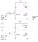
I implement it by 4 MOSFET (2xN-ch, 2xP-ch) as an H bridge. The problem is with the voltage levels: to change one set of FETs (P + N) I need 5v or 0v – which I don’t have (MCU GPIO=3.3v). I tried to add 2xnpn transistor to drive the MOSFETs (ugly solution) and it didn’t work at all.
I added the circuit that I used; can anyone help my in designing this driver? Or have other solution to my problem (remember – low cost and power).
Thanks,
Nir
I need help in designing a latching relay driver. The relay is single coil and need 5v @ 200ma. The problem is that my MCU uses 3.3v GPIO.
The system must be extremely low cost, and consume as little power as possible.
I implement it by 4 MOSFET (2xN-ch, 2xP-ch) as an H bridge. The problem is with the voltage levels: to change one set of FETs (P + N) I need 5v or 0v – which I don’t have (MCU GPIO=3.3v). I tried to add 2xnpn transistor to drive the MOSFETs (ugly solution) and it didn’t work at all.
I added the circuit that I used; can anyone help my in designing this driver? Or have other solution to my problem (remember – low cost and power).
Thanks,
Nir
Attachments
-
 27.7 KB Views: 41