Boondocker
New Member
Hello All,
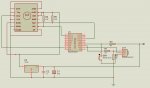
I went ahead and purchased a PCB mount SCP1000 D11 pressure sensor. So far I’m unable to obtain the raw pressure data into an 18X chip using the i2c commands. The result sent is 65535. I’ve doubled check the circuit and attached photo and PCB carrier link.
In reviewing the manual under Readi2c it explains “ If the i2c hardware is incorrectly configured, or the wrong i2cslave data has been used, the value 255 ($FF) will be loaded into each variable.” I believe some communication is occurring because when I change the slave address, from %00100010 to %00010001, the data ready (DRDY) remains at zero and will not proceed to out of the Rdychk loop.
After closer reading the datasheet, on page 12, it states the raw pressure output is between 120000 and 480000. The result is larger than word variable. Is this the problem? If so, is there a solution?
Any help and suggestions are appreciated.
Thanks,
Boondocker
http://www.vti.fi/midcom-serveattachmentguid-a5eab1b6104f11dd83cf7774ee6a7f057f05/tn38_scp1000_test_pcb_carrier_rev_1.3.pdf
http://www.vti.fi/midcom-serveattachmentguid-e9735f5baea5692c3b9753f9069511c7/scp1000_product_family_specification_rev_0.08.pdf
I went ahead and purchased a PCB mount SCP1000 D11 pressure sensor. So far I’m unable to obtain the raw pressure data into an 18X chip using the i2c commands. The result sent is 65535. I’ve doubled check the circuit and attached photo and PCB carrier link.
Code:
'18X  Program for barometeric pressure
'i2c SCP1000D11 Sensor
'Slave address 0x11- %00010001


Symbol DRDY=input1  		' Data Ready from sensor

Symbol TempOut = %10000001    ' 0x81 Raw Temperature, 16 bit retrive
Symbol DATARD8 = %01111111    ' 0x07 Raw Pressure, 8 bite read
Symbol DATARD16= %10000000    ' 0x80 Raw Pressure, 16 bite retrive


symbol Mode = %00001010      ' 0x0A- High Resolution, continue
'symbol Mode = %00001001     ' 0x09- High Speed,continue
'symbol Mode = %00001011     ' 0x0B- Ultra Low Power, Continue
'symbol Mode = %00001100     ' 0x0C- Low Power, Trigger


Pause 500

I2cSlave %00100010, I2Cslow, I2Cbyte  'selects i2c device, set clock speed,  word
I2Cwrite %00000011,(Mode)                 'sets mode in operation address 0x03

Pause 45
Rdyck:					        'Data Ready Check
  If DRDY=1 then Press
  Pause 10
  Goto Rdyck

Press:

I2cSlave %00100010, I2Cslow, I2Cword

I2cRead DATARD16,(b1,b0)
SerTxd( "Raw Reading = ", #w0, CR, LF )

Goto RdyckAfter closer reading the datasheet, on page 12, it states the raw pressure output is between 120000 and 480000. The result is larger than word variable. Is this the problem? If so, is there a solution?
Any help and suggestions are appreciated.
Thanks,
Boondocker
http://www.vti.fi/midcom-serveattachmentguid-a5eab1b6104f11dd83cf7774ee6a7f057f05/tn38_scp1000_test_pcb_carrier_rev_1.3.pdf
http://www.vti.fi/midcom-serveattachmentguid-e9735f5baea5692c3b9753f9069511c7/scp1000_product_family_specification_rev_0.08.pdf
Attachments
-
![php2CBHINPM[2].jpg](/data/attachments/3/3559-7b2c9574101db38e17cb14f1966e6948.jpg) 49.7 KB Views: 30
49.7 KB Views: 30
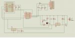
") Normal convention is to have positive voltages at the top and ground at the bottom, and for power supplies to have the input voltage at the left and output voltages at the right.
Normal convention is to have positive voltages at the top and ground at the bottom, and for power supplies to have the input voltage at the left and output voltages at the right.