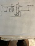
one fuse is in series with the 115V supply as it first enters the charger. the other is is just before the output to the fence wire
So like this, which makes sense to me ...
Code:
                                             .---------.---.
          F1    .-----.   .-------.    F2    }---------   .|.
115V >---O==O---| PSU |===| PULSE |---O==O---^---------   | | Very
 AC  >----------|     |   |  GEN  |----------.            |_| High
                `-----'   `-------'        __|__  _ _ _  __|__
                                           /////         /////
That 'very high' resistance is air, reduced by rain, livestock leaning on the fence to try and turn themselves into burgers, and jokers who may throw metal chains onto the fence. That, plus lightning strikes, may blow the F2 fuse, and that's what we need to check is blown or not..
There are two ways; checking across the fuse or by checking if the voltage pulse is reaching the fence.
I can understand why it was thought having a separate battery supply for the PICAXE and measuring across the fuse looked to be safe, seemed to be isolated. But it is not, not when one pin of the PICAXE also connects directly to ground, nor when connected to the other side of the fuse, is floating in air is connected to ground by a very high resistance.
Some sort of 'neon parallel to the fuse' could work, but emulating one of those pulse detectors which simply hangs on the fence is probably easier, better, and safer. The software is simple; if no pulse is detected for a couple of seconds turn the LED on. That's just a few lines of PICAXE code.
The challenge then is detecting the pulse. For 'hang-on' monitors I would have guessed there's some sort of inductor which produces a pulse when the fence is pulsed, maybe some sort of in-line capacitor circuit. The magic solution being a single signal pulse of low enough voltage that the PICAXE can detect without damage and large enough that it can tell that signal is there, relative to its own isolated supply - no direct connection to ground, except through air.
In practice, most circuits I found used a direct connection to the fence, via some large value mega-ohm resistor voltage dividers, direct or via an op-amp comparator to a digital input or ADC. Avoiding false pulse detection seems to be challenging in some cases, from mains or radio, so there may need to be some experimentation and the code might not be quite so simple as first imagined.
I would still favour some sort of opto-isolator in there as that guarantees the PICAXE never being exposed to excess voltage.
")