How to drive 48 bulbs?

BeanieBots

Moderator
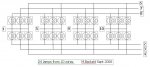
I have a requirement to control 48 incansecent bulbs.
They are 2.5v @ 300mA each.
They are to be arranged in two sets of 24.
Only one bulb from each row will ever be on at one time.
The lamp unit must be easily detacheable from the controller using as few wires/connections as possible and ideally with no silicon in it.

I have 5v and/or 12v available at the required current but would prefer to use the 5v.
The "information" is available from an I2C device and is simply read and then displayed, so the PICAXE can spend most of it's time displaying if required.

My quandry:-
If these were LEDs, I'd simply multiplex, probably using a 2803 darlington and six PNPs driven via a 1-of-8 (74HC138) all controlled by a 28X/1. That would only require 14 wires to connect.

Unfortunately, as these are incanescent, such an arrangement would require a diode in series with each bulb. This would require a second board (with connectors etc) to facilitate the 48 diodes. Wiring would be a nightmare!
Also, the extra 0.6v volt drop would mean I wouldn't have enough drive (after mux'ing) to use the 5v line.
I can just about get away with 50% duty via two trannies from 5v. (The 2803 volt drop is pushing it.)

If I drive each bulb independantly (6 off 2803 plus latches), it would be rather a lot of chips and require a 49 way capable connector. That is not acceptable.

I'm too close to this to see the chips for the bulbs.
If anyone has any suggestions on how to drive these bulbs with the above restrictions, it would be appreciated.
 

Andrew Cowan

Senior Member
Using shift registers and darlingtons? True, it wouldn't be 'no silicon on board', but it would only need three control wires.
 

BeanieBots

Moderator
That's another option, but it would be 12 chips on board:eek:
No much different to latches+Darlingtons really but thanks anyway.
I'm edging towards fitting the 48 diodes. Maybe as part of the wiring loom rather than a board. (Oh.. how tacky!)
 

BeanieBots

Moderator
Unfortunately they MUST be incandescent bulbs.
Thanks for the link though. Good prices, will be changing a few torches:)
 

Jeremy Leach

Senior Member
Might be making a stupid blunder, but here's my thoughts...

Code:
    o    o    o    o    o    o    o    o
    |    |    |    |    |    |    |    |
  .-o----o----o----o----o----o----o----o.
  |                                     |
  |                 2803 Driver 1       |
  |                                     |
  |                                     |
  '-o----o----o----o----o----o----o----o'
    |    |    |    |    |    |    |    |
    V    V    V    V    V    V    V    V
    - D1 - D2 - D3 - D4 - D5 - D6 - D7 - D8
    |    |    |    |    |    |    |    |
    o    o    o    o    o    o    o    o


 .-----------------------------------------.
 |  .    .    .    .    .    .    .    .   |
 |  |    |    |    |    |    |    |    |   |
 | .'.  .'.  .'.  .'.  .'.  .'.  .'.  .'.  |
 |( X )( X )( X )( X )( X )( X )( X )( X ) |
 | '-'  '-'  '-'  '-'  '-'  '-'  '-'  '-'  |
 |  |    |    |    |    |    |    |    |   |
 |  o----o----o----o----o----o----o----o   | X 3
 |                      |                  |
 |                    |/                   |
 |                   -|                    |
 |                    |<                   |
 |                      |                  |
 |                     .-.                 |
 |                     | |                 |
 |                     | |                 |
 |                     '-'                 |
 |                      |                  |
 |         o------------o------------o     |
 '-----------------------------------------'
You have two 2803 drivers, driven directly from 28X2 picaxe (when available!). That's 16 outputs. You have 6 NPN transistors again driven from 28X2. That makes 22 outputs in total from 28X2.

Each driver has a diode on it's output as shown above. From cathode of each diode is connected 3 lamps (3 times the stuff in the dotted box).

I expect I've messed up, but 'think' it's ok !
 

BeanieBots

Moderator
Jez, I may have missed something, but besides requiring a 28X2, isn't that the basic multiplex method that I described originally which has the problem of requiring a diode in series with each bulb?:confused:
I'll study it a bit more because you only use 2*8=16 diodes. (I think).
 

premelec

Senior Member
I think I'd try shift registers and logic level MOSFETs with CLK DTA protocol and fast data transfer... whatever works... SMD components would be quite compact [5v line power]. Don't forget the initial current is about 10x the running current on the incandescent lamps...
 

BeanieBots

Moderator
The MOSFET shift register idea is probably the best idea from a technical point of view but that's one hell of a lot of silicon (48 MOSFETs alone) AND it would need to be within the lamp unit which something I desparately want to avoid. 2803 + 6 PNPs + 48 diodes would (I think) be a lot cheaper. Only the diodes would need to be within the lamp unit.
I'll have to test to see if I can get away with that amount of volt drop.

Jez, can't wait for the 28X2. In both aspects of the phrase!
 

Dippy

Moderator
How are going to do it without semis?

A minimal amount of semi would be a servo, magnet and 48 reed switches :)

or 3 off 4-16 decoders plus transistors.. oh silicon again.
 

BeanieBots

Moderator
You missed the point.
I don't want semis (requirement for PCB to be more precise) on the lamp board and not too many wires back to controller.
If they were LEDs, no problem, just bring back the mux lines. 8+6=14
Can't mux bulbs the same way, so, either 48+1 lines or add diodes to make bulbs 'look like' LEDs.
 

Dippy

Moderator
Yes, I missed the point. I must have missed several points as I don't see how an off-board shift register or X2 is going to help(?).

So, a lamp board with 48 lamps, no semis at all on lamp board, one bulb-at-a-time, and not too many wires back to control board. Quite a conundrum. Maybe a light bulb part-time Charlieplex.

I've probably missed it again. Maybe an 'ideal' schematic would help.
 
Last edited:

BeanieBots

Moderator
It's all in post #1 Dippy. (at least, I thought it was)
Maybe I should emphasise.
Two modules, controller & lamp.
Need to be seperable. Hence, requirement for (expensive) connectors.
If lamp module only has lamps (no silicon) then only requires wire loom & connector. Otherwise, requires PCB+mounts+construction.
48 bulbs, only 1 out of each bank of 24 on at any given time.

If, (and it's a great big IF), the bulbs were LEDs. It would be VERY easy.
14 wires (IDC or 15W-D) back to controller, 2803+6 off PNP, job done.

If I fit 48 diodes (one for each bulb) in the lamp unit, it can still be done that way (subject to volt-drop tests). The problem is how to facilitate 48 diodes in the lamp unit. (and cost).
If no diodes, then controller would require (current capable) driver for EACH lamp plus associate logic (many chips) to control 48 lines AND 49 lines between lamp unit and controller. (big expensive connectors).

At the moment, the 48 diode option sounds the cheapest/easiest with the diodes being part of the internal cable loom.
 

Jeremy Leach

Senior Member
Maybe BB, if you told us what the lamps were all for (fairground?) we could come up with something that did away with the lamps entirely :) Like a moving beam or something !! Just joking.
 

BeanieBots

Moderator
Hmm... don't really want to go down that path Jez.
OK, I'll confess, they are not actually lamps. They're micro cathode heaters.
The rest is secret.
Moving beam is much closer than you think!
 

Mycroft2152

Senior Member
Hmm... don't really want to go down that path Jez.
OK, I'll confess, they are not actually lamps. They're micro cathode heaters.
The rest is secret.
Moving beam is much closer than you think!
BB,

The only google reference for "micro cathode heaters" is for a miniaturized Xray device.

Using the Picaxe for a medical device?
 

BeanieBots

Moderator
Those of you who know what I do for a living can probably guess what it's for and will also know why I won't (can't) say any more. Sorry, but that's just the way it is. It's not medical.
 

Mycroft2152

Senior Member
Those of you who know what I do for a living can probably guess what it's for and will also know why I won't (can't) say any more. Sorry, but that's just the way it is. It's not medical.
Careful BB, if this is a work related (commercial) project, then you are getting very close to the very line that our dear friend Ciseco crossed.

As a former R&D department manager, I would be less than impressed, during evaluations with an engineer that looked for a solution to an engineering problem by going to a user group on the internet.

Myc
 

boriz

Senior Member
A minimal amount of semi would be a servo, magnet and 48 reed switches :)
Genius! Though I think he needs two servos and two sets of 24 reeds. Would only require 4 wires to the 'lamp' module.

Otherwise, how about one of those bar drivers normally used for LED VU displays. It takes one of it&#8217;s output&#8217;s high based upon the level of a single analogue voltage. You should be able to find one that has at least 24 outputs. Of course, you would need a transistor on each to get the current high enough for your filaments. That would also only require 4 wires.
 

BeckettM

New Member
Beanie
There is another possible solution, that involves Matrixing of the lamps.

(Its very early in the morning here so the thought process isn't fully active)

A quick look at it gives 24 lamps individually controlled with 10 wires.
6 wires are common to the lamps, while 4 are controlling the ON

Electricity (AC or DC) is good at only flowing where there is a path, and if you control not only the voltage source but the return path, it can be useful.

If you imagine 3 lamps off a controllable voltage source (wire 1), and you control each lamp (wires 2,3,4), if you apply power to wire 1, and control wire 2 only one lamp will illuminate.

If you double the lamps using same control (wires 2,3,4) but add a second controllable source (wire 5), you have a quarter of your system.

Another 3 control wires (wires 6,7,8) and 6 lamps using the same voltage source (wires 1,5), gives 12 lamps off 8 wires.

Double again adding just 2 additional voltage control wires (wires 9,10), and connecting the lamps to the existing 6 control wires (wires 2,3,4,6,7,8), gives a total of 24 lamps with only 10 wires.

Effectively its a 4 x 6 matrix.

It becomes useful if you want to display banks of lights, as well as a single lamp.

To drive it you can use a latch which controls either the Voltage, or the control, and is addressed by the one Micro-P chip

Hope this adds to your solution.
Cheers
Mark
 

boriz

Senior Member
All 24 driven by just two wires and no semis !

A resonant LC ‘tank’ circuit consists of a capacitor and inductor in parallel (TC). The impedance seen by an AC signal fed to this TC is low for all frequencies EXCEPT the resonant frequency (fR).

With two TCs in series, tuned to two different frequencies, the voltage developed across each will be about half of the total (like a resistive divider with two roughly equal resistors), until the frequency of the incoming current matches the fR of one of the TCs. The voltage across THAT TC increases to a much larger value than the voltage across the other TC. (like a resistive divider with one resistor much smaller than the other)

You make 24 TCs in series with a bulb across each. The AC current comes in on two wires, and the frequency determines which bulb gets the power. Not very efficient, but it might just work.

fR=1/(2*pi*SQRT(LC)) where L=inductance and C=capacitance.
 

BeanieBots

Moderator
BeckettM, I'm hoping you're right and that's along the lines of what I was hoping for. Unfortunately I don't quite get it. Would be great if you could do a diagram. So far, all the matrix solutions I've thought of simply don't work unless the 'lamps' have series diodes which gives the problem explained earlier.

Boriz, I like your way of thinking!
If only it were possible. With a large resistive element (the lamp) it would not be possible to get the 'Q' of the tank circuit good enough to distinguish between so many lamps. Might work with just a few though.
 

boriz

Senior Member
How about series LC? All units in parallel, each unit consisting of bulb+L+C in series? Same principle.
 

BeckettM

New Member
Beanie
Attached is a crude drawing (sorry at work and MSword is about all there is to draw with).
using a matrix method, to switch on one lamp at a time.

By careful consideration and choosing how many wires are voltage source, and how many are control, you can switch more than one at a time.

Normally I use a latchs (74LS373, etc) to store one set of data, then switch latch, and store the other data, then let rip.

For the 6x4 matrix a single 8 output device is all the processor required.
(I have done this before using a clock, bcd counter and eprom to store the pattern.)

If you use AC to power the lamps, then if you use a zero cross detector (ie AC voltage is at zero), to switch, then you won't get the switching spikes, that generate interference.

For your 2.5 volt lamps this may not be necessary (but is useful background info)

Hope this helps.
Cheers Mark
 

Attachments

BeanieBots

Moderator
Sorry, don't see how that will work.
Let's number the lamps in your diagram from left to right and refer to top and bottom row (T & B) so that the top left hand bulb is T1 and the bottom right hand side is B12.
Now let's say I want to turn on T1. To do that, I take node 1 high and node 8 low. Voltage is now applied across T1. However, current will also flow through B1,B4 & T4 also B1,B7 & T7 and B1,B10 & T10.
This matrix method works well with LEDs, but not with incandescent lamps.
 

BeckettM

New Member
Beanie
It hasn't become obvious to you ...yet.
Current only flows if there is a path.

If you put 3v on wire 1 (common to T1,2,3,4 B1,2,3,4), but only connect wire 8 to ground (negative) then only T1 will illuminate.

Leaving 3v on wire 1 but connecting wire 4 will illuminate B4

If you put 3v onto wire 10, and still had wire 8 connected to ground, then T10 would illuminate.

Remember that to light a lamp (or LED) you need current to flow. If there is power but no ground, then there is no current flow.

You may get a very small leakage around the other lamps, but since its 3x the impedance
you will never see them illuminate...

cheers
Mark
 

alband

Senior Member
Don't know if I've missed the point here but I've got one..
I'm doing something like this now. Trying to control a 7X7 grid of bi-colour LED's. Each LED work in both polarities but give a different colour.
I had previously built a minikit from maplin that had a 5X7 display of ordinary LED's. After studding it's circuitry hard I found that the only way you can achieve true diversity of which light to put on when is to do them one at a time.
Imagine a 4X4 square of bulbs. The negatives of the two left bulbs are connected to one pin (on an 28X) and the negatives of the two right hand bulbs are connected to another pin. The positives of the two top bulbs are connected to another pin and the two positives of the bottom bulbs to the last pin. (I know there are no +'s or -'s on bulbs but it's just easier to say that). All the negative are tied to high by a resistor and the positives tied to ground by a resistor to stop any bulbs going on when they shouldn't. To make them light you do them diagonally one at a time using a sort of grid reference approach. Make the corresponding pins high and low and the bulb will light.

Attached is the code for every possible combination of lights; each combination being triggered buy a switch on pin 3.

Hope that helps.
 

Attachments

BeanieBots

Moderator
BeckettM, I know it's been a few years since I took my electronics degree, but I think I remember that little bit we did about ohms law.

Let's take your circuit and see what the "leakage current" might be.
Assume each is resistance R and the voltage is V.
The current for the "ON" bulb would be V/R.

Now let's consider bulb B1.
Bulb B1 has resistance R and is in series with 3 lots of two seriesed (if that's a word) other bulbs. So that's R + 1/3(R+R)=1.67R. So the current for the "off" bulb would be 0.6 of the current for the "on" bulb.
That's some "leakage current"!

alband, yes, you've missed the point. A matrix only works if the driven elements are diodes. What you describe is a very common method of driving such devices but unfortunately won't work with incandescent bulbs.
 

BeckettM

New Member
Beanie
Theory is great, and all I can say is that lamps have differing ON and OFF resistances.

Maybe you should try it to see if the "unintentional" current is enough to illuminate the unwanted lamp (B1).
Light output is not linear from a lamp, and while there may be "unintentional" current flow in one or more lamps, it should still appear OFF.

If you are driving this "lamp array" from DC, then there should be no reason why you can't add a diode in series, which then negates any "unintentional" current.

After all 48 diodes is still cheap, and presumably the supply can easily be adjusted to compensate.

Cheers
Mark :)
 

BeanieBots

Moderator
Well thanks for your efforts BeckettM, but 60% is not an option.
If you read the whole thread you'll notice that these not actual lamps but micro cathodes which have very similar characteristics. 48 diodes might not be be expensive but having to produce a board and mount it in the unit (under the conditions required) would be. None the less, I fear that the 48 diode option is my only realistic option.
 

BeckettM

New Member
Beanie
Fair enough. I did read the micro cathodes bit, but wasn't sure if it was intended as tongue in cheek.
You could probably get away with the diodes being inserted into the wiring, with a bit of heatshrink over the joint and diode as one.

Good luck.
Mark :)
 

radcom

Member
micro cathode heater

I think micro cathode heaters are used in a special type of electronic valve used before transistors were as widely used as today
 
Last edited by a moderator:
Top