help with axe033

jwsparkes

New Member
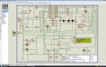
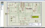
Can you please help me with the VSM simulator and the AXE033 module. I have developed a program for the picaxe 28X1 using the AXE033 module and serout commands. The program works fine in the programming editor but does not produce correct LCD output in the VSM software. In summary the program is for an "brush" electroplating amp-hour monitor. The user inputs the charge to be plated via a push button, and the program counts down the charge as it is plated and then opens the circuit when the charge has been deposited.

Please see the attached VSM and program file.

Can you advise on any help and point me to where I can find the version id of the VSM software? (I read somewhere on the forum that it's not under "help about").

I am running Vista.

kind regards, James.
 

Attachments

Last edited:

Technical

Technical Support
Staff member
The AXE033 is not a complete model as it was not created by Revolution. We are working on a better model at present. At present it only supports T2400 and does not have the special time/msg functions.

However in your program it should be fine if you use T2400 instead on N2400.

You could replace all 'N2400' in your program with 'LCD_baud' and then have the two lines (one of the two always commented out)

symbol LCD_baud = N2400
'symbol LCD_baud = T2400

at the top of the program. This makes it easier to swap between real and VSM.
 

Technical

Technical Support
Staff member
The PICAXE model revision numbers are shown in the simulation log file after you have run a simulation.
 

jwsparkes

New Member
Thanks Tech,

I'm sorry, but my code does use T2400 throughout and not N2400. The problem still persists.

Actually, the product won't be using an AXE033 but a generic LCD with the FRM010 driver module that I purchased from MicroZed here in Aus.

I understand that you are working on correcting the AXE033 modle in the VSM software, but in the meantime, is there a way that I can "trick" the VSM software to work correctly?

I am somewhat disappointed at this time, because I have purchased the VSM software to complete this specific project (all the advertising for the software stated that it supported the AXE033 module) and all I have achieved is the creation of a rather messy wiring schematic.

I can further summaries the program as follows:

On startup, the prog 1 button on IN4 is used to cycle through the charge input. Each press cycles through 0 to 9 for the hundreds, tens, and units. A hold for 3 seconds stores the digit and moves on to the next digit. Similarly, the program then prompts for the units Amp-seconds, minutes or hours.

The program then enters the main loop and monitors the voltage and current and calculates the delta charge in each loop and subtracts it from the set charge (if the switch on IN6 is open). The button on IN5 is not used at present.

When the charge has reached zero, the relay is opened and a buzzer sounds.

Can you please provide any advise to help me out?

Kind Regards,

James.
 

Technical

Technical Support
Staff member
What is exactly the error you are experiencing with the LCD - the model should work with all the commands you are using? Have you tried the example circuits provided with VSM that use the LCD module (e.g. AXE110 datalogger)

Also your program should have a 'high 0' right at the very start to put the serial line in the correct status (idle high) for use with 'T' baud rates. Otherwise the very first serout will be corrupt.
 
Last edited:

jwsparkes

New Member
Hi Tech, thanks for your response. I didn't know about setting the serout pin to high. Unfortunately that didn't correct the error.

The error that I am experiencing is as follows. On program startup the LCD is supposed to output:

SET CHARGE
000As

the left most digit is supposed to be flashing and this outputs fine in the editor simulator, but in the VSM simulator, I get the following

SET CHARGE x
000Axxs (where the "x" are corrupt characters)

and instead of the first digit flashing, both the first and the second digits flash, but not in sinc. Pressing the "prog 1 button" correctly updates the first digit and cycles through 0 to 9. When the prog 1 button is held closed for 3 seconds, the second two digits flash, but then pressing or holding the prog 1 button does nothing. I have attached a screen grab for you to see.
 

Attachments

Technical

Technical Support
Staff member
We'll pass this info on to the lcd model manufacturer. The second digit flashing looks like a cursor issue, but this looks like is a bug in the simulation model.
 

fernando_g

Senior Member
I'm also experiencing similar problems

I'm also experiencing similar problems (jumbled characters on the AXE033) so I will also be waiting for a software patch!

Other than that, I'm very happy so far with the product.

Thanks!
 

pbutton

New Member
I have occassionally had this problem with the simulator and overcame it by adding a
"pause 50" command after the serout. This seems to let the LCD keep up and avoids weird
characters.
 

fernando_g

Senior Member
I solved the problem by adding a couple of lines at the very beginning, right before the main program loop executes:

serout 2,t2400,(254,1)
pause 30

This only needs to be called once, and the AXE033 model will work just fine
 
Top