BeastFromTheEast
New Member
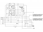
It's taken a little while, but I have managed to build a 3 axis headtracker using a PICAXE 08M2, the um-FPU V2 maths co-processor and a Pololu IMU-9 inertial measurement unit.
The small circuit board at the top is the IMU. Other chips are fairly obvious. During construction I grafted on additional wires to allow the um-FPU to be programmed remotely - these have been removed for the picture.
** Have noticed only one picture is allowed - Ian **
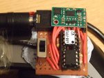
Headtracker mounted on VR goggles. Note sticky tape strain relief for cables!
The IMU consists of a 3 axis gyroscope, 3 axis accelerometer and 3 axis magnetometer, on a small PCB with some voltage regulators and through-holes for soldering onto header pins. This allows it to be interfaced fairly painlessly with the PICAXE via the I2C interface.
In use the PICAXE harvests the accelo and magno data from the IMU, and uploads it to the um-FPU, which works out the absolute angles xy, xz and yz. The PICAXE also works out what quadrant the angles lie in (as the V2 cannot work this out on its own). The PICAXE then gets the gyro data from the IMU and uploads it to the FPU, where it is integrated to give an instantaneous reading. The end results are readings around all three axes, using the gyro readings (which are nice and smooth, but not referenced to the absolute readings), and a small contribution from the accelo/magno readings (which stop the end results from wandering too far away from the absolute values).
The PICAXE also applies a centering routine which allows the readings to be centred at a particular orientation. The serial download cable is used to send the output bytes back to the PC (one FF sync byte, and 3 0-FE positional bytes, one for each axis), where they are picked up by a program called PPJoy. This mimics a USB joystick, and a second program (GlovePIE) is used to mimic a TrackIR headtracking setup. When the simulator is run, it latches onto the (virtual) TrackIR and locks the cockpit view onto the incoming headtracker data.
As you can see from the pictures I have mounted the circuit on top of a pair of VR goggles using Blu-Tac (!!!!). It is best to attach the cables to the top of the PC, so there is a sufficiently large loop to allow head movement without tangling with anything or pulling the wires taut.
The circuit could easily be adapted to other applications (such as walking robots) where you want to add a sense of balance. An early version of the program (prior to the co-processor being involved) read back 3 16 bit words to the serial terminal (0-65535 for 0-360).
Ian
The small circuit board at the top is the IMU. Other chips are fairly obvious. During construction I grafted on additional wires to allow the um-FPU to be programmed remotely - these have been removed for the picture.
** Have noticed only one picture is allowed - Ian **
Headtracker mounted on VR goggles. Note sticky tape strain relief for cables!
The IMU consists of a 3 axis gyroscope, 3 axis accelerometer and 3 axis magnetometer, on a small PCB with some voltage regulators and through-holes for soldering onto header pins. This allows it to be interfaced fairly painlessly with the PICAXE via the I2C interface.
In use the PICAXE harvests the accelo and magno data from the IMU, and uploads it to the um-FPU, which works out the absolute angles xy, xz and yz. The PICAXE also works out what quadrant the angles lie in (as the V2 cannot work this out on its own). The PICAXE then gets the gyro data from the IMU and uploads it to the FPU, where it is integrated to give an instantaneous reading. The end results are readings around all three axes, using the gyro readings (which are nice and smooth, but not referenced to the absolute readings), and a small contribution from the accelo/magno readings (which stop the end results from wandering too far away from the absolute values).
The PICAXE also applies a centering routine which allows the readings to be centred at a particular orientation. The serial download cable is used to send the output bytes back to the PC (one FF sync byte, and 3 0-FE positional bytes, one for each axis), where they are picked up by a program called PPJoy. This mimics a USB joystick, and a second program (GlovePIE) is used to mimic a TrackIR headtracking setup. When the simulator is run, it latches onto the (virtual) TrackIR and locks the cockpit view onto the incoming headtracker data.
As you can see from the pictures I have mounted the circuit on top of a pair of VR goggles using Blu-Tac (!!!!). It is best to attach the cables to the top of the PC, so there is a sufficiently large loop to allow head movement without tangling with anything or pulling the wires taut.
The circuit could easily be adapted to other applications (such as walking robots) where you want to add a sense of balance. An early version of the program (prior to the co-processor being involved) read back 3 16 bit words to the serial terminal (0-65535 for 0-360).
Ian
Last edited:
")