Forum newbie - second picaxe project - help!

sr

New Member
Hi all, im Simon. :)

Ive started a new project which is basically a webcam pan/tilt thing powered by servos. Here is a quick model i made with google sketchup:


I have had success in the past with picaxes, I made a pet feeder with a servo and 2x16 LCD display, and that worked just fine, using a Picaxe 18A.

This time I have an 18X, and it works in the pet feeder circuit.

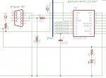
The webcam project schematic:


Now, the problem is that the computer won't 'talk' to the picaxe AT ALL! I have a USB-Serial cable (not from rev-ed) and it works with the pet feeder.

The parts list is here:

https://www.rapidonline.com/bundleselection.aspx?id=26

I was wondering if anyone has any idea why my PC wont talk to my picaxe..? :(

I wondered if my resistors were the wrong type / rated too low.
 

hippy

Ex-Staff (retired)
Staff member
Powering the PICAXE through the LED (D1) is a little unusual but I guess should work. I can't see anything wrong with the circuit beyond that.

It could be a mis-wiring on the 9-way D. Check you haven't got the RX/TX crossed-over or counted pin numbers from the wrong end - If it's a female socket you have 2 and 3 swapped over.
 

sr

New Member
Thanks for the reply :)

Ive checked about 99999999999999999999 times the connections are all ok :(

What do you think to the resistor hypothesis?
 

hippy

Ex-Staff (retired)
Staff member
Unless the resistors are wired in the wrong place or wildly out of spec I don't see a problem with them.

My money is still on having the 9-way D wired wrong. There's a checklist in one of the manuals for helping to solve download problems and a forum search should also help.
 

sr

New Member
Ive checked and re-checked the connections, ive rebuilt the circuit six or seven times from scratch, and ive checked the serial cable connection against the tiny little numbers on the plastic connector. Any other ideas? I have looked at the manuals, no luck. What do you suggest I search for, I did search before I posted this but other people seem to be having issues because they have wired things up wrongly etc, and mine is wired correctly..:(
 
You shouldn't put the LED in series with the chip VDD. This lowers the voltage and restricts current.

Bypassing the LED should fix it.
 
Last edited:

sr

New Member
I have tried it both with and without the LED, the picaxe gets 3.5v with the LED and 5v without and either way the computer wont talk to it :(
 
Just bypass the LED for the moment. Are you sure the picaxe is the correct way in? Try turning it 180 degrees or maybe try the 18A
 
Last edited:

hippy

Ex-Staff (retired)
Staff member
There's the download checklist in Manual 1 which you can also work through. If everything is wired correctly you should be able to see a signal on Serial In when running the Comms Test from the Programming Editor.
 
The parts list in RAPID shows a 5V LED. I assume that it is the LED shown in the circuit. If you drop 5V through the LED the Picaxe is starving.
 

moxhamj

New Member
I agree with Hippy. Pin 2 and 3 are not right. Attached is a screenshot of piece of a working schematic. The D9 is a female. I built an "extension lead" = male to female so I didn't have to reach behind the computer all the time. Computer is male. So output of extension lead is also male. And this plugs into a female on the board. Pin 3 should go via the resistors to physical leg 3 on the picaxe. Also pin 2 on the D9 goes to physical leg 2 on the picaxe. A useful coincidence?

Also the led is going to drop 1.6V at least, which means the reset pin will have 1.6V more on it than the picaxe power supply. That is not right. Leave out the led, or wire it another way if you want indication power is being applied.

I do like the idea of using a D9. Ok, it isn't what rev-ed suggest. However, my local supplier (Electus) lists the D9 right angle solder plug at 47c and the stereo download plug at 38c. I can afford the extra 9c. But I do a lot of picaxe work where I am flipping between programming, and communicating via RS232 to the picaxe on other pins (with a max232) using VB. It is very useful to have the same plug. Also, even though the RS232 only uses 3 wires, it is very handy to wire up things like extension leads using rainbow cable and IDC plugs. Just put them in the vice and squeeeze. Takes less than a minute. I also like having a standard D9 male plug on a lead at the front of the computer. Doesn't matter if it is an extension lead, or a USB to D9. Very useful.
 

Attachments

Last edited:

Dippy

Moderator
Yes, it looks like you've go the connections to D plug pins 2 and 3 the wrong way round.
D type pin 2 is the Rx for the PC and pin 3 is the PC's Tx.
Try reversing them.

And yes, they are generally very good quality connectors. A bit big for a lot of apps.

Maybe checking 99999999999999 times wasn't enough?

And sometimes 'trying something out' is quicker than incorrect checking.
 
Last edited:

sr

New Member
Thanks for the responses guys, I will try your suggestions tomorrow and let you know how it goes.

:)
 

sr

New Member
Excellent, it's working now! It appears I did have pins 2 & 3 wired wrongly. Somehow I thought that pin 2 on the picaxe went to pin 3 on the D9, and pin 3 on the picaxe to pin 2 on the D9. I must have got confused when looking at the manual as the numbers are obviously different for each download cable. Ah well. Thanks. :)
 

moxhamj

New Member
Excellent. And your picaxe survived, which shows how robust they are as you would have had minus 12V on an output pin. Please let us know how the project develops.
 
Top