FETs keep dying

Andrew Cowan

Senior Member
Hi all.

I am building a robot for my AS systems and control project. I am trying to control 36V 750W motors using STP55NF06 FETs (60V, 55A).

I am driving the FETs using a 4427 driver.

The first time I wired it up, the FETs worked fine. The next day when I came into school, both FETs were shorted Drain to Source. I replaced them, and all worked again.

Next time I tested them, I found one was had a 1.5 ohm short between Gate and Source. I replaced them both, and they worked fine.

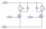
However, I am now on FETs number 5 and 6. Has anyone got any idea why they are blowing? It was suggested that other students have been turning the motors - but I don't think that this would have damaged the FETs as the FETs are not connected when I leave the robot - they are left as seen in the schmatic below - with no connectors connected. I think this means that even if a voltage was created across the motor, it wouldn't go across the FET.

Any ideas?

Andrew
 

Attachments

BeanieBots

Moderator
Are the catch diodes still intact? If they are the wrong type, they might have blown early on and the FETs are being over-volted.
Is the diagram shown left unplugged?
If yes, then the gates may be static damaged. Fit a high value (100k) resistor between gate and 0v.

Get a scope and check the voltage across the FET when working. If the diodes are not fast enough, they might not start to conduct before excess voltage kills the FET.
 

Rickharris

Senior Member
Alternativly replace the motor temp with a non-inductive load e.g. a light bulb and see if the FETs blow - if not then the motor is to blame (or others.)
 

Andrew Cowan

Senior Member
I've replaced one of the motors with a multimeter and load resistor. The diodes (200V 10A) still work.

I leave it all unplugged, with the batteries taken out.

Andrew
 

gengis

New Member
If you are unplugging it and leaving the gates floating (unconnected) you probably need to look no further than that. You may have a static charge that exceeds the gate breakdown voltage and when you make the connection that kills the gates. You need to protect them with a snubber or some fast diodes. Likewise the freewheeling diodes across the motor have to be fast enough to snub the transients. Inductive loads present mosfets with spikes from the brushes and it is always good practice to use a small ceramic cap across the brushes. Lastly read up on it - lots of application notes detailing how to do what you are doing. It is not as trivial, or as simple, as it might seem. I had an instance where a 15 amp fuse wasn't protecting a 50 amp mosfet, or so it seemed. What was killing the mosfet was the inductive spike in the 3 feet of wire between the fet and fuse.
 

Andrew Cowan

Senior Member
If I added a 100K resistor to remove static, what would I connect the other end to? The aluminium case?

Both times when the FETs have blown, the 4427 drivers have not yet been conneced. Do the 4427 drivers feature something to stop this? (the gates will always be connected to the FETs).

Andrew
 

Technical

Technical Support
Staff member
No just to 0V, ie the 100k goes between the PICAXE/FET gate connection and 0V. This also stops the gate 'floating' whilst the PICAXE initialises.
 

BeanieBots

Moderator
If I added a 100K resistor to remove static, what would I connect the other end to? The aluminium case?

Both times when the FETs have blown, the 4427 drivers have not yet been conneced. Do the 4427 drivers feature something to stop this? (the gates will always be connected to the FETs).
Andrew
The 100k should go between gate and 0v. (J2.1 on your diagram)
It's the fact that the drivers were not connected that caused the problem. If they are ALWAYS connected, then the problem should'nt happen. The fact that you have a connector and they COULD be disconnected means you should fit the resistors even if you never intend to disconnect them.
 

Andrew Cowan

Senior Member
As I disconnect the batteries when it is not in use, this means 0V doesn't exist. Does this matter, or J2.1 good enough?

Thanks for solving this problem.

Andrew
 

BeanieBots

Moderator
You need to prevent the gate voltage from exceeding gate/drain or gate/source limits, so connecting to J2.1 is what is required.

This will only solve the problem if it is static causing it. You should fit the resistors anyway even it does not solve your problem, as static is the most likely cause even if not the actual cause. One less potential problem. Pun intended.
 

boriz

Senior Member
750W is a lot. I'd be tempted to use two MOSFETS in parallel for each motor (total 4 MOSFETS). And lots of heat sinking.
 
Top