DS18B20 troubles! pls help

Paolo1986

New Member
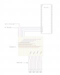
I have purchased 2 x DS18B20 temperature sensors hoping to connect it up with a 28xI. I have followed the wiring diagram provided in the basic command manual. I have tried the two following programs;

PROGRAM 1
main:
readadc 0,b1
pause 1000
debug
goto main

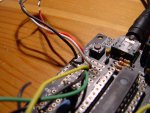
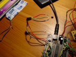
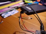
When using this program I get a value of 254 in b1 that is constantly displayed no matter what the temperature is. The sensor is receiving 5V and I am using a voltage regulator 7805. The data line is reading 4.98V constantly. The 4K7 resistor is in place between the data and positive line.

PROGRAM 2
main:
readtemp 0,b1
pause 1000
debug
goto main

When I use this program everything is the same apart from I get a value of 0 in all b variables.

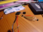
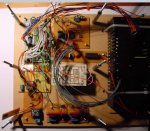
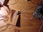
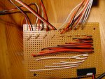
I feared my soldering iron may have been too hot for the sensor, therefore I used a connector block to connect up a new unused sensor however I experience the same results. I have also tried it without connecting the positive to the sensor as on the datasheet it states it is not necessary, but still no joy. I tried to put some Pics up but my putfile isn’t working at the mo so will do as soon as I can. Any help would be much appreciated as I have nearly spent an entire day scratching my head.
 

eclectic

Moderator
"I tried to put some Pics up but my putfile isn’t working at the mo so will do as soon as I can. "

Paolo.
Please use

Manage Attachments

in the Submit Reply section.

e
 
Last edited:

Paolo1986

New Member
dont you just love it when things work!!

why why why?!?!? How come you have to use input C0 i thought these were reserved for the 40x not 28x. So if i wanted to connect multiple temperature sensors would i use C1, C2, C3 and so on. THANK YOU SO MUCH, i was getting ready to use thermistor if all eles failed. Thanks again!!
 

eclectic

Moderator
why why why?!?!? How come you have to use input C0 i thought these were reserved for the 40x not 28x. So if i wanted to connect multiple temperature sensors would i use C1, C2, C3 and so on. THANK YOU SO MUCH, i was getting ready to use thermistor if all eles failed. Thanks again!!
Paolo.

Please read manual 1, page 82.

And yes, you can use

readtemp 0,b0
readtemp 1,b1
readtemp 2, b2

and so on.....

e
 

Paolo1986

New Member
manual 1 page 82 is about flowcharts

In regard to multiple temperature sensors when you interface them you connect them to digital inputs rather then analogue inputs. I always imagined digital inputs would be either on/off. So this also means if i were to leave the connections the same i could of changed the coding to;

main:
readtemp porta pin0, b1
pause 1000
debug
goto main

and it would also work? Thanks again much appreciated
 

eclectic

Moderator
In regard to multiple temperature sensors when you interface them you connect them to digital inputs rather then analogue inputs. I always imagined digital inputs would be either on/off. So this also means if i were to leave the connections the same i could of changed the coding to;

main:
readtemp porta pin0, b1
pause 1000
debug
goto main

and it would also work? Thanks again much appreciated
1. Please download the latest Manuals. (PICAXE Manual near the top of this page)

2. No. The program will NOT work.
Please use the Programming Editor Syntax Check.

e
 

Michael 2727

Senior Member
A DS18B20 is a Digital Device, it communicates serially to a Micro or PC and
Readtemp and Readtemp12 are Digital commands, serial In/Out communication.
(most of the DS chips used on this forum are also)

A Thermistor, LDR, Pot, Touch Screen are Analogue devices (resistive) they
use the ReadADC, ReadADC10 command which converts an analogue value to a
digital value between 0 to 255 or 0 to 1023.

Analogue values can be used on a digital input but-
The analogue equivalent of a Digital Low = 0 to 84 or there abouts.
The analogue equivalent of a Digital Hi = 168 to 255 or there abouts.
Any Analogue value between (84 to 168) may give an unusual or random
result if used on a Digital input.
 

westaust55

Moderator
why why why?!?!? How come you have to use input C0 i thought these were reserved for the 40x not 28x. So if i wanted to connect multiple temperature sensors would i use C1, C2, C3 and so on. THANK YOU SO MUCH, i was getting ready to use thermistor if all eles failed. Thanks again!!

on the 40X/40X1, PortC is the extra port available for use as inputs and outputs and portB is for the "normal" inputs.

with the 28X/28X1, there is no port D and thus portC is used for the "normal" inputs.


For both the 28 and 40 chips portA is for the ADC (analog) inputs. the 40X also has a few extra ADC inputs on portE.


and yes, use c0, c1, c2 etc
 
Last edited:

Paolo1986

New Member
Continuation of interfacing the DS18B0

I am going to start again to save confusion, I have been trying to interface 4 DS180B temperature sensors with a 40x for a small project to monitor and control heating around the home. I have created a stripboard to hold the pull up resistors, I am using a power regulator and connected to the mains.

I have two circuits

i) 28x + stripboard (connected to 4xAA)
ii) 40x + stripboard (connected to mains)

The only differences between the two circuits are the size of the circuit and the power source. I have provided schematics for the 40x but only drew part of the circuit as it is a pretty large circuit. All sensors are pulled up by 4k7 resistors.

When I connect the stripboard and sensor to my 28x all works as it should, I took readings at the chip and the sensor which both correlate.

Supply Voltage = 4.3
Data line voltage = fluctuates between 3-4V

However problems start to occur when I connected the same stripboard to the 40x circuit, I get no reading and the voltages at both ends are;

Supply Voltage = 4.56
Data line = 4.53 constantly

What would cause the DS180B to sustain a constant voltage on the data line?
Do you think 4.5V isn’t enough Voltage given the size of the circuit?


The coding is very simple and is;

main:
readtemp 0,b0
readtemp 1,b1
readtemp 2,b2
readtemp 3,b3
debug
goto main
 

Attachments

Last edited:

westaust55

Moderator
DS18B20 troubles

Please upload a schematic of your circuit. It will be easier to understand how you are connecting the four DS18B20’s.

From the photos, are you using the correct resistors?

In post 13, the left photo shows at the top 4 resistors which to my eye sight are brown-black-yellow = 100K not 1K or 4.7k.


In post 14 right photo seems to have a resistor coloured orange-purple-yellow = 370k.
Plus a yellow-purple-brown = 470 Ohm and one brow-black-red = 1kOhm


A 1kOhm resistor has the colour code brown-black –red


A 4.7kOhm resistor has the colour code yellow-purple-red.

You should be working with a 4.7kOhm resistor for each DS18B20.


Is it possible to damage the sensor if you connected the 4k7 between the supply and ground?
will not help make the circuit operate but will not damage the DS18B20 or resistor.

From the datasheet:
The 1-Wire bus requires an external pullup resistor of approximately 5kΩ.
Albeit that you say you have had it working, I would think that use of a 1kΩ resistor may effectively be too strong a pull up resistor on the one-wire data line and prevent the signal pulling the line low enough for a low state.


You indicate:
I have been trying to interface 4 DS180B temperature sensors with a 40x for a small project to monitor and control heating around the home.
how long and what size are the wires to the remote DS18B20 sensors?
I presume the voltages you measured are at the PICAXE end?
Could voltdrop at the DS18B20 end be the problem?
 
Last edited:

Paolo1986

New Member
changed original post

how long and what size are the wires to the remote DS18B20 sensors?

The length of the wire is 3 meters and the thickness is about 1 mm.

I presume the voltages you measured are at the PICAXE end?
They are the same at either end measured at both ends to be sure


Could voltdrop at the DS18B20 end be the problem?

I dont think so as the three meter cable is also connected to the 28x which is powered by 4xAAs

Thanks for the comments and help all very much appreciated
 

Paolo1986

New Member
Problem SOLVED!

OK so here is what the problem was, when using the 40x the DS180B only works on portd, so pins 19,20,21,22,27,28,29 and 30. I was using portc and therefor was not getting any readings. DOH!

Thanks everyone for your interest and help

cheers
 

westaust55

Moderator
DS18B20 troubles - SOLVED

OKay great to see you have worked it out.

Back at Post 1 you mentioned a 28X1 chip. With the 28X and 28X1, port C is the normal inputs.

But as you are now using a 40X (same for 40X1), port D is the normal inputs and port C is an extra port with more limited control/commands as you found out.

All as stated back in post 11
 
Last edited:
Top