Drawing Program for PICAXE Circuit

Clive Wallis

New Member
Hi,

I am urgently looking for a simple circuit drawing program, suitable for a small circuit which includes a PICAXE 18X, a few resistors & some connectors.

Must be easy to learn, preferably free or low cost. Preferably includes symbol for 18X.

Output file must be suitable for standard graphical packages, eg JPG, BMP.

I don't require PCB layout.

What software do you use for circuits?

Any suggestions would be much appreciated.

TIA

Clive
 

Andrew Cowan

Senior Member
I use Diptrace (free).

Although it doesn't come with PICAXE chips, you can add them by downloading them from this forum (see in miscellaneous finished projects).
 

leftyretro

New Member
Hi,

I am urgently looking for a simple circuit drawing program, suitable for a small circuit which includes a PICAXE 18X, a few resistors & some connectors.

Must be easy to learn, preferably free or low cost. Preferably includes symbol for 18X.

Output file must be suitable for standard graphical packages, eg JPG, BMP.

I don't require PCB layout.

What software do you use for circuits?

Any suggestions would be much appreciated.

TIA

Clive
I like ExpressPCB, it has both PCB layout and Schematic drawing as seperate programs. The schematic program lets you store custom components that you then only need to draw once and have avalible on any new drawing. It's free of course.

Link: http://www.expresspcb.com/ExpressPCBHtm/Download.htm

PS: Lets see if I can attach a simple example of a drawing I made a while back:


Lefty
 

Attachments

Last edited:

MBrej

Member
Im surprised no ones mentioned EAGLE yet, it has a very large component database, and you can download more libraries from here. It does take a bit of getting used to, and there is a limitation of 1 page for schematics on the freeware version, but thats not much of a problem

Matt
 

manuka

Senior Member
WHY THE NEED ? In my experiences this usually dictates the layout technique-articles will usually redrawn by the publisher anyway. You've no doubt seen mags. saying " even schematics on the back of an envelope may be acceptable" !

For much draft work & educational handouts etc almost any drawing program will do- Windows "Paint" or even the graphics editor in "Word" etc. The choice often boils down to your platform, preference & ability to put in the learning time. CadSoft's EAGLE ( Easily Applicable Graphical Layout Editor) is certainly versatile (running on Win,Linux & Mac) but the learning curve may be too steep for your simple 18X needs. In the past I've pointed the likes of cash strapped students with old clunker PCs to such classics as the mid '90s Paint Shop Pro & MGI PhotoSuite SE (Starter Edition) etc. These -gasp!- W95 beauties are now so ancient that copyright issues are usually "incidental". Photo editing software that comes with many digital cameras & scanners etc can often be quite suitable.

IMHO a particularly important electronic need however relates to the program's ability to easily elaborate on the layout. Suitable text comments can typically relate to component ID & pinouts,polarities, supply voltages, power ratings etc- all the sort of boring (but confidence boosting) info. that those low in experience often REALLY need shown to help ensure a circuit will work. I'm a bit of a fanatic about this, having tasted the agony of defeat myself (preteen) due to circuitry assumptions that "everybody knows". Of course you all want to know just what these were!! I shudder to recall, but they arose due to my thinking the trimmers on a variable tuning capacitor were the screw terminals! It was some time later before a kindly "elmer" pointed out the blunder (& incidently got me fired up seriously).

Given the abundance now of digital cameras, circuit layouts often really justify a picture along with the schematic. Us old hands tend to forget symbols are often inconsistent with the component size - even a lo-tech. toggle switch may be physically huge, & need placing in an unusual position for operator convenience.

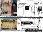
EXTRA: Check the 20M screen grab below - recently drawn by MGI PhotoSuite SE software that came with my first Sanyo digital camera (1997).
 

Attachments

Last edited:

mikie_121

Member
I second the vote for EAGLE. The one page limitation has never limited me yet. A pinout for the 18X is simply a PIC16F8* or you can use an DIL18 socket

I found ExpressPCB to be annoying and I couldn't get the pcb layout out of the program easily. It wanted me to send it to their own PCB company (at great expense).
 
Last edited:

hippy

Ex-Staff (retired)
For simple you cannot beat 1/4" graph paper, pen and scanner.

When I had to design relatively complex circuits before they went to the people who could use the CAD software I used to photocopy a good quality page of standard components ( A4 enlarged to A3 ), cut out components, tack mount them to A3, draw the connections then photocopy reduce to an A4.

These days I tend to use ASCII Art.
 

moxhamj

New Member
Ok, here is one from Eagle. Just for interest I timed this one - took 4 1/2 minutes to draw. Picaxe library has all but the 20M. Enjoy.
 

Attachments

Last edited:

Mycroft2152

Senior Member
They are all good pcb drawing programs. Try them out, and find one that works best for you.

After working with it for a while, you will become very speedy in drawing schematics.

I've tried them all. For me DIPTRACE was the easyist to learn and use. I agree with Stan, shaped based symbols are easier to layout and remember. That was tyhe reason for the DIPTRACE library thaI created and posted on the forum.

Myc
 
Last edited:

manuka

Senior Member
Yah Hippy-I'm an old 5mm grid/"Twink"/gluestick fan myself, but you can't beat modern electronic cut & paste! Draft 18X circuit below,dating from ~2003 & drawn by MGI PhotoSuite SE, may suit the original poster's needs?

Dr_A: My "EAGLE" eye spotted "US$1" above your 18X- was this a deliberate mistake to test us?
 

Attachments

Last edited:

westaust55

Moderator
DIPTRACE is my recommendation.

After MyCroft mentioned DIPTRACE in this forum, I downloaded the free version (all features available - just a 250 hole limitation) and within the first evening have a reasonable A3 sized schematic prepare.

There is a very good pdf tutorial than can be downloaded.

Mycroft has provided his library with the PICAXE components and other related items and I have also uploaded a small librarty for other useful parts.
http://www.picaxeforum.co.uk/showthread.php?t=10576

Recommendation: give it a go. For many hobbists, the 250 hole limitation is almost no limitation.
 
Last edited:

Clive Wallis

New Member
Many thanks for all the advice

Hi,

Many thanks for all your replies. I'm overwhelmed by so many :)

Before posting I had tried ExpressPCB. This seemed fairly simple to use, but it didn't always do what I expected. Eagle appeared to be more complicated to use. I guess both programs would do what I want, given enough practice.

I'll certainly have a look at DIPTRACE and the library of symbols for PICAXE. I'll also look at ASCII Art &Tech-chat.

In answer to Manuka's comment 'Why the need?' , I write for a small technical news/letter which doesn't have any staff to do graphics. If I submitted the circuit on a fag packet, that's how it would look :)

In the past I've drawn circuits with pencil & paper, and pasted text from my printer. Copied with a photo copier, touched up with correction fluid, and then scanned.

I feel that it's now about time I tried to do this by computer.

Regards

Clive
 

kranenborg

Senior Member
To add something else to the list: I use sPlan 6.0 from a German company called ABACOM (previously I used MS Powerpoint). Not for free (39 Euro), but gives very nice schematics and allows own extensions to be added to the library. Furthermore I get results very quickly. A free trial version can be downloaded from their website at http://www.abacom-online.de/uk/html/splan.html

Two examples are included as attachments
/Jurjen
 

Attachments

Last edited:

Tom Rose

New Member
Hi,

I am urgently looking for a simple circuit drawing program, suitable for a small circuit which includes a PICAXE 18X, a few resistors & some connectors.
Call me crazy but I use an older version of Corel Draw for both circuit drawing and PCB layout.
I set preferences for move at 1/10th of an inch. Draw a line between connections, add a node or two and adjust. Easy and quick. I have a library of parts.

You can get an older version of corel off good old ebay.

Printing to velum on a laser printer gives you a great contact negative for positive coated boards for contact exposure using a cheapo uv light from Lowes.

Resist removal is diluted lye from Lowes.

Etch from lots of vendors including rat shack.

From design to board in a couple of hours.

Drill with a dremel, because of my poor eyesight I have mounted a dino microscope (attached to the computer I use to program with) with the cross hairs set to match
where the drill lands.

Tom
 
Top