Darlington trasistor

RubiksRune

New Member
Hi.
Im trying to build this HDD clock http://www.ian.org/HD-Clock/

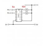
My picaxe is 5v, my RGB LEDs are 12v, and I have a ULN2803AG

In the tutorial above, he's using a ULN2003A, but the only different between mine and hes, is 7 and 8 darlington transistors..so mine should do the work as well?

anyhow, I can't figure out how he does it, how does he controll the 12v LED with the picaxe? I got 0v at ground, 12v at +, but the picaxe doesn't trigger the transistor.
 

Dippy

Moderator
You posted this in the wrong section.

But, yes, your 2803 should be fine. Spend some time studying parameters on Data Sheet.

As for how the rest of it works, I'll leave that for someone with a spare couple of hours.
Looks nice.
 

inglewoodpete

Senior Member
I must presume that you RGB LEDs are common anode?

Common cathode RGB LEDs are unlikely to work with the ULN2803 or ULN2003.

Refer to manual 1: Standard Circuits 2 - Using a Darlington Driver IC.
 
Last edited:

Dippy

Moderator
So is removing unwanted 'write' statements eh Manie :)

But seriously, it looks a pretty project.
 

Rickharris

Senior Member
Let me put it this way. Is it possible to use 5v on the ULN2803 input, and get 12v on the output!?:confused:

My RGB LEDs are common cathode

Thanks for the answers!:)
You can regard the 2803 as a switch, it is turned on/off by the 5 v signal from the picaxe and allows current to flow through it - The source of that current may be higher then the 5 volts from the picaxe up to the max rating of the 2803.
 

inglewoodpete

Senior Member
Darlington 101

In addition to what Rick has written, perhaps we should go back to darlington basics.

The darlington transistor in the format used into ULN2003 and ULN2803 are a switch to the 0v rail. In addition to my earlier reference to manual 1: Standard Circuits 2 - Using a Darlington Driver IC, have a look at manual 1: Standard Circuits 1 - The Transistor Interfacing Circuit.

This describes the darlington configuration at little better. Also have a look at my simplified diagram below. Note that the V+ connection to pin 9 of the ULN2803 is only used for protection of the darlington transistors: it can't be used to supply loads.

The common cathode RGB LED has a -ve connection: the cathode. The 3 anodes must be connected towards the +ve supply (obviously with current limiting resistors). As you can see from the diagrams, the ULN2803 can't supply a positive voltage to its output, only sink current to 0v.

Your options are to use common anode RGB LEDs or use a push-pull driver like the L293D. The L293D has 4 outputs, 3 of which will need to connect to the 3 anodes of each RGB LED.

Peter
 

Attachments

Last edited:

BeanieBots

Moderator
Let me put it this way. Is it possible to use 5v on the ULN2803 input, and get 12v on the output!?:confused:

My RGB LEDs are common cathode

Thanks for the answers!:)
Put simply. NO. (taking your question litterally)

However, it IS possible to use a ULN2803 to control a 12v load.
Don't forget, the ULN2803 is an inverter, so applying 5v to the input will make the output go to 0v. (or at least close to 0v).
It is an "open collector" output. That means it cannot source any current, so applying 0v to its input will make the output look like an open circuit. There will be no volts unless a load is connected. The voltage seen will be whatever voltage the load is connected to.

As already mentioned, your LEDs must be common anode.
There is a PNP version of the NPN type ULN2803 which can be used to drive common cathode type LEDs but I can't remember the number. Google should be able find it.
 
Top