Cant get started - no downloads working...

emdanx

New Member
Hi All,

First post here, total newbie, sorry for the basic problem...but I'm stuck...

I've bought a 08M, built up the download circuit as per various instructions. The circuit looks correct. I've got 3xAAA batteries delivering the 4.5V.

The download resistors, 22K and 10K seem to be placed correctly.

In the Programming Editor, the serial connection "test" works, ie I measure VDC on serial in pin and ground, and press the little LED icon. The voltage switches from -0.6VDC to 4.5VDC each time I press the icon.

But trying to download the code, always comes up with "Error hardware not found on Com2...".

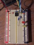
I've attached a photo of my breadboard...

Any help appreciated!
 

Attachments

moxhamj

New Member
Layout looks fine to me. My computer works on COM1, but if you are getting a voltage change then it sounds like the com port is correct. Can you measure the volts coming out of the serial port before it goes through the resistors. Just check it is -9 or -12V. Some computers output lower negative voltages.
 

emdanx

New Member
Layout looks fine to me. My computer works on COM1, but if you are getting a voltage change then it sounds like the com port is correct. Can you measure the volts coming out of the serial port before it goes through the resistors. Just check it is -9 or -12V. Some computers output lower negative voltages.
Thanks, I'm using Com2 because its easier to access on my PC. I get the same result if I use Com1.

I've measured the volts between out of the serial lead, and its -10.5V.

I don't know if this is weird or not, but... my order from my supplier says "picaxe 08m pic12f683i/p", and the chip supplied says 12f683i/p on it. If I google 12f683i/p it points to Microchip.com, which would appear to be a different chip altogether.

Have they sent me the wrong chip?
 

emdanx

New Member
Hi emdanx,
The 08M is what you have got. PICAXE chips are based on Microchip PIC's.
Grant
Oh, thanks. I sort of was hoping it was wrong, so I could explain why the circuit won't work! Back to the drawing board...

It doesn't need anything to be done to go into "program" mode does it? You just apply the power, and start the download?

Do I have to set the PC's serial port properties in a particular way?
 

emdanx

New Member
Got it, thanks all!

OK, so I worked it out, 'twas a bit stupid of course. The negative battery lead was plugged into the wrong rail on the breadboard. Swapped it over, and it works!

Thanks for everyone who replied, it allowed me to narrow down on what might be wrong! Thanks again.
 

moxhamj

New Member
Brilliant. Pls post any more questions as we love helping beginners get "hooked" on picaxe!

BTW many silicon chips would be dead if you connect them backwards, but picaxe seems to cope ok esp if you use batteries. Great to hear it survived.
 

westaust55

Moderator
emdanx,

If I read correctly, you did not have the voltage reversed - does not appear to be in the earlier photo.

What you found was that the two rows of breadboard holes encircled with black are not connected internally (that is they are two separate sets of conenctions).


A good find and well done.

I guess I do not use a bread board too often, frequently go straight to protoboards and having noticed some photos of breadbords (including commercial versions) have the two groups of holes down the sides encircled in red and black resectively, might also have thought they were internally connected.
 

emdanx

New Member
What you found was that the two rows of breadboard holes encircled with black are not connected internally (that is they are two separate sets of conenctions).
Yep, that's it. I circled those rows with texta myself! I did assume the two rows were connected...oops. I didn't guess that the circuit wasn't getting powered up at all!
 

BCJKiwi

Senior Member
On that board under the 'Texta' there is a red line and a black line to indicate +v and 0v at both edges of the board.
 

BeanieBots

Moderator
Glad you found the problem quickly and there is a lesson to be learned.
Whenever we ask people to take voltage measurements, we usually ask that they are done AT THE ACTUAL CHIP PINS. If you had measured the supply voltage AT THE PINS, you would have found it even quicker.

Welcome to PICAXE.
 

lbenson

Senior Member
As per BJC, it often makes for easier wiring if +V and 0V are present on both edges of the breadboard--+V with the red line adjacent and 0V with the black or blue line adjacent.
 
Top