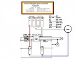
Brief overload (not overloaded briefs)

westaust55

Moderator
I did not see a specific motor only current rating.
The data I spied included:
Working Voltage: 2.5 to 3.5Vdc
Rating Current: 200mA

Switch signal: 3.3V
100ms
But at either 100mA or 200mA the answer is DO NOT DO IT !

Each PICAXE IO can handle 20mA so you are drawing at least 5 times and likely 10 times the IO rated current. Heck many PICAXE chips are only rated to a total current of 95mA.

Even for just a few msec (thats 1 or 2 not 100msec will likely result in damage.


You need to add a darlington transistor, moto driver IC or similar.
There are PICAXE project boards that already include these devices.
 

212

Senior Member
Fooey...yep, I kinda figured that, was just needing someone to tell me out loud. I should have posted a different ad, one of them says it only uses 100ma when activated. But...like you said, DO NOT DO IT !
 

hippy

Technical Support
Staff member
Plus that's 100mA when running, the start-up in-rush current could be much, much more.

You could parallel-up PICAXE outputs to give a higher-current drive, but you're still over-stressing the chip. You can try it, but I wouldn't expect the PICAXE to last long.
 

marcos.placona

Senior Member
Just use a darlington and don't put picaxe under all the unnecessary hassle! If you wire it up the correct way, you'll just have an extra IC laying there (ULN2003 maybe), and won't have to care about changing the picaxe every now and then when it fries due to over-stressing
 

Andrew Cowan

Senior Member
Isn't the problem with the ULN2003 that it acts as a high sided switch? I find that it is annoying when using a project board with a ULN2003 if you want to control something that uses lots of current, and already has a common negative - eg an LCD backlight.

Andrew
 

Dippy

Moderator
High sided Andrew?

I can't really see a big issue/problem here unless a mountain is required from a molehill. I would use a transistor to switch it, but never power it direct from PIC.
 

hippy

Technical Support
Staff member
I may be wrong but my understanding is, and description indicates, that a high-side switch is one which sits above the component switching +V into it ( in terms of traditional circuit diagram layout ), whereas a low-side switch sits underneath the component effectively switching 0V, but basically both allow current to flow or not.

ULM2003 and most Darlingtons and transistor switchers are low-side, high-side being the rarer option.

The advantages of high-side are that power can be switched on or off to components which may have more than one 0V, typically automotive bulb circuits, and that 0V's remain connected, I/O remains relative to 0V even though unpowered. The difficulty ( for non-IC high-side switches ) is the complexity of circuit needed to get it to work.

The disadvantage of a low-side switch is that I/O remains relative to the +V even when not powered and there may also be 'virtual 0V' lines created through other I/O. This isn't usually a problem for switching bulbs, relays and motors but can be when switching semiconductor modules. It's also true that 'virtual +V' lines can be created with a high-side switched module, but with I/O 'at 0V when off', that feels 'a more natural state of affairs'.

I've never been comfortable with the idea of low-side / darlingtons switching power to LCD's, TX and RX modules but that could just be because I'm not an eletronics engineer and don't know enough about it and it seems to add complexity ...

The ULN2003 should be able to switch an LCD 0V and backlight 0V together as suggested but you'd have to make sure that any pull-downs on LCD I/O went to the switched 0V not to circuit 0V and it's likely necessary to set all I/O lines to the LCD module high when it's not powered.
 

marcos.placona

Senior Member
High sided Andrew?

I can't really see a big issue/problem here unless a mountain is required from a molehill. I would use a transistor to switch it, but never power it direct from PIC.
I second that, and in regards to power it, using the pic to power it would be unnecessary overkill
 

premelec

Senior Member
If you DO need a high side switch that is accomplished by using two transistors - an NPN and a PNP - the PNP takes the current and has it's emitter to V+ and collector to load. A resistor from the PNP to V+ and a second resistor from PNP base to NPN collector with NPN emitter to V-. The drive is into the NPN base through a 1K resistor... 3 resistors, two transistors less than a $1. Not so much trouble and saves your PICAXE...
 

gengis

New Member
Like others, I'd just add a switching transistor.

But there is a trick for just that application. You only need high current for a brief time. The way to get that without overloading the driver (should the timing be wrong) is to use a resistor that limits the current to something the Axe can handle then bypass the resistor with a large capacitor to provide that high current spike . The cap is discharged through the resistor and then appears to be a dead short for a brief time until it charges when the line goes high.

That technique is useful and frequently used in driving relays - takes a lot of current to pull the armature into a closed position but only a small amount to hold it closed.
 

212

Senior Member
The little gadget I wanted to power just uses a small solenoid to move the lens. It needs the voltage reversed to make it go back and forth as needed, according to whether it is day or night. I was also thinking I may be able to use the charged cap idea, because I have those, but could not figure out how to reverse it too.

I had the order ready, and almost hit the pay button, when I thought I should ask you guys the question. I don't even know if it can be used with the cameras we use yet. Another guy went ahead and ordered one, so I have a little while to figure out how to work it now lol... I did find some schematics that use a bunch of transistors and diodes, but see that the motor drivers have all that built in.

The Sony cameras we use for trail cams have a lens cover that automatically opens when you power it on. I bored a hole in one of them and put in an IR cut filter. This uses an actual motor to open and close it, so once I get this question solved, I can use the same thing to work the Sony...which uses a lot more power I'm sure. Oh, we convert the cameras to see IR light so we can use them at night without spooking the animals with the flash. Problem is...the pictures are all red with the IR cut filter removed.

I appreciate the replies, and I do listen....pretty good...usually. When I don't, it ends up costing me....
 

Dippy

Moderator
Can I just get something cleared up for the listeners .. maybe it's only me that is confused(!).

"The Sony cameras we use for trail cams have a lens cover that automatically opens when you power it on. I bored a hole in one of them and put in an IR cut filter."

You have a Sony camera with automatically-opening cover.
And , originally, when the cover opened the picture was good?
You have now bored out the lens cover and inserted some IR transmissive plastic?
So, the cover/IR filter is only closed when the camera is OFF?

"so once I get this question solved, I can use the same thing to work the Sony"
.... eh? Are we talking about a different camera now?

So with the cover closed you view the IR spectrum?
But I thought you said the cover opened when you switch the camera ON?
So, therefore, the camera has to be OFF to close the cover and therefore your IR lens.

"Problem is...the pictures are all red with the IR cut filter removed."
- at this point my brain powered-down and my cover closed...

Are we talking Sony or a.n.other make of camera now?


Sorry to sound dense... it is Sunday.
 

gengis

New Member
The cap charging idea will work for open-closed but will require two (totem pole) outputs on the Axe. One non-polarized cap resistor, but two I/O channels of the Axe, or four transistors and one channel.

The cap/resistor technique is really useful for things like reed relays that only change state infrequently - but that seems to describe the IR filter since it is night/day(?). The boon comes in when using batteries to power relays and wanting to conserve power. It may take 25-100 ma for the relay to close and only 5-10 to hold it closed.

If your lens/filter requires two pulses of opposite polarity it doesn't continuously eat power (and from what I was able to glean from the datasheet).

Post some circuits. I'd like to see what you are doing. And what camera? I'm using el-cheapo cameras that don't do date and time - and I'd like to detect movement (ships, cars, bridges, people, out to 500 yards, daylight only). I haven't figured that out completely, but it looks like a lens and pair of photo diodes is promising or perhaps a color sensitive set of three leds working as photo diodes.
 

212

Senior Member
I wondered about the non-polarized caps...that really means you can use them either way around?? Cool! I'll start a new topic about the other camera stuff. Wow! 500 yds is pretty far!


Hmmmm...Sunday here too, I forget to describe things well enough....good enough...whichever. The link I posted on the first page is to use on another type camera...not a Sony. Hoping to use it on a "Jazz DV150" and/or cheap board cameras.

To change a Sony P series (P31. P32, P41...etc) , to an IR camera, we remove the original IR blocking filter from between the CCD and lens assembly, and replace it with plain glass. Now the camera sees IR light. You can now cover the flash with IR pass material, and the camera will see the light given off. The pictures will be very red now though, day and night.

OK, the cameras have an auto lens cover, like I said. We normally open it up and disconnect it so the camera doesn't make the noise when opening it. So now the lens cover is just in there open all the time, camera on or off.

I installed an IR cut filter, removed from another camera, into the lens cover on the Sony...P32 in this case I can operate the lens cover...now IR filter...manually, with wires connected to the little motor that moves it. I have not, yet, been able to have it move itself as needed. I want the IR block filter in front of the camera lens during daylight hours so I can have full color pictured during the daytime. All this is something as an aside, I put this one away a few years ago....unfinished. If I can control the gadget in the link, the same thing should work the Sony lens cover/IR cut filter.
 

westaust55

Moderator
Like others, I'd just add a switching transistor.

But there is a trick for just that application. You only need high current for a brief time. The way to get that without overloading the driver (should the timing be wrong) is to use a resistor that limits the current to something the Axe can handle then bypass the resistor with a large capacitor to provide that high current spike . The cap is discharged through the resistor and then appears to be a dead short for a brief time until it charges when the line goes high.

That technique is useful and frequently used in driving relays - takes a lot of current to pull the armature into a closed position but only a small amount to hold it closed.
Flooby,

Concur wuith MyCroft - a great suggestion.

In model railway layouts the capacitor discharge method is often used to provide a burst of energy into the small coils for operation points (turnouts for the US contingent) and then the current drops to a trickle if the switch is left/jammed on ON to prevent burrnout of the small coil.
 

gengis

New Member
I wondered about the non-polarized caps...that really means you can use them either way around?? Cool! I'll start a new topic about the other camera stuff. Wow! 500 yds is pretty far!
There are ready made non-polar electrolytics used for speaker crossovers or you can connect two (matched) caps plus to plus, or minus to minus. With two equal series capacitors you only get half the capacity. If you have the room, a non-polar foil/film cap may be a choice.

That Jazz DV150 Looks like a good choice. I haven't found all the specs for it, but the people owning them seem pleased with the results.

I used a Aiptek Megacam 1.3 for camera # one and Aiptek PocketCam X for # two. I've got a CDS photocell on #2 to shut it down during nightime. It is in a small waterproof enclosure and runs from 3 AA batteries and will take 1,000+ SVGA shots on a charge over a period of 10 days or less. I mount it around the city and take pictures where it looks interesting. Camera 3 is in the planning stages now. I want some way to detect movement of boats, ships, vehicles (the reason out to 500 yards - camera will be that far from the ships). The Aiptek website had the best deals $10 for 1.3 mp, and $ 20 for 2.1 mp. I see where they have a video camera for $ 30 now, but haven't researched it.

Jazz also brands some of the Aiptek line (or visa versa).

Some enterprising soul should sell the bare camera guts and provide detailed connection info on them. There seems to be a market in the trail cam, rocketry, model plane, balloon, and kite aerial photography, for that sort of thing.
 

Dippy

Moderator
A Doppler device won't give you range finding, which you would need.

And by the way, Doppler device aren't too good at things moving perpendic accross your field of view. A passing seagull or low-flying biscuit would trigger it unless you have some fancy processing for range/size/speed etc. You would need some clever things for ships at 500m. Of course you can do it.
 

eclectic

Moderator
Apologies Dippy.
I should have inserted a "tongue in cheek" icon in my earlier post.

But, seriously, the kit looks cheap, for an up-market toy to play with.

Hmm? Camera trigger :- for passing seagulls?

e.
 

gengis

New Member
Interesting idea the radar doppler detector. I actually bought and built the speed gun kit some 10 years ago. It worked, but wasn't very sensitive. The 130 ma/12 volts would be hard to supply with batteries.

One of the objectives is keeping it small and unobtrusive. Two concerns there 1. someone might come along and take it 2 "homeland security" is getting ugly here. Even the coast guard - once friendly and helpful, are acting like arrogant gestapo now.

I'm guessing that an X or K band radar emitter would be detected by the ships own radars, and that may cause me problems.

Then as Dippy pointed out, this would be passing perpendicular to the field - and docking ships aren't fast by any means. I watched a typical docking from my kayak - really close up. It took three tugs the better part of two hours to get the ship snugged up where they wanted it (for liquid transfer, probably fuel). Containerized stuff may be more forgiving or some docks may make mooring quicker.

What I did do that is looking good: I took one of those center tapped cadmium sulphide photo cells and put it at the focus of a lens in a piece of tubing painted black. I can watch the output from the two sides and have it trigger a circuit (using op amps and comparing the balance) when it changes. Basically the same thing a PIR detector does, but without the Fresnel lens to make multiple zones.

I do get some false triggers from lightening, grass movement etc.. The lightening is infrequent enough and light reflecting off the water or grass movement may be corrected by careful positioning of the lens tube - or another idea that bears some experimenting is using the output of LEDs used as photo detectors - they output close to their operating voltage (red is good for 2.1 V and blue 3.1V) when detecting light of the same color (they all "see" white light, but are most sensitive with their own color)

I'm thinking the color thing might be used to advantage (even though most ships are white, gray or black).

Using a lens in a tube narrows the angle of the sensor, which is good for my purposes, but makes it hard to aim. It isn't like I can spend a lot of time fooling around with camera placement - jab it into the ground with a sand spike - or (worse) take the time to screw the mounting to some structure - great but takes longer. If I spend time screwing around getting everything perfect I'm afraid of attracting attention.
 

Dippy

Moderator
I've got to ask this question as I keep seeing people on about it:-
Why use LEDs when you can get extremely sensitive photodiodes?
Apart from one or two novelty apps I honestly cannot see the point.
Can someone educate me please?

Maybe some food for experiment are the linear photodiode arrays.
Or just get a dsPIC, a synch separator, a cheap video camera and play - just kidding.
 

gengis

New Member
Hi Dippy

In my case economy. I like to try to get things to work with the parts on hand. In all cases use some commonly available part versus a boutique part. And there's the matter of spending $6 to ship a 50 cent part - so hopefully try to get all parts from a stocking distributor, not have them trickling in for a week or two, from several sources.

A specialized part, if I order a spare, will just sit around until I forget when it is for. Sensitivity is only one parameter, not the only parameter.
 

Dippy

Moderator
Oh, money. Fair enough.

Well, in some applications you'll need sensitivity . And if you buy a part for a specific job why would it "sit around until I forget when it is for" ??

(Having said all that, I've got loads of parts that I have sitting around... And having said that it's sometimes nice to have things sitting about as you'll never know when you'll need them. I really must stop arguing with myself.)
 

gengis

New Member
I may have inadvertently led you astray with the talk about op amps. The op amps weren't for signal gain but to detect the change in balance. Looking at the "right now" signal and comparing it to the signal several seconds ago.

Parts wise I have a room (literally) full of them. I seldom throw out anything that could be used. Very little is cataloged; I can usually remember where it is. Generic parts are around in sufficient quantities that they get into bins and drawers - specialized parts are another matter - the best is an envelop with the part name and specs scribbled on them and they join the other hundreds of those. Or they sit plugged into spare breadboards, or just get lost.

One of the reasons for using op amps . . . I was having some trouble getting the 14M outputs converted into ADCs and running low on variables. But this is more along the lines of "proof of concept" - using visible light to sense (slow) motion (of large objects) from a long distance.
 

212

Senior Member
I never got just how to use the cap discharge to provide enough power to run a motor with the Picaxe, so I did this instead. This does work good, but I'll keep messing with it. See anything wrong with it before I post it to the trail cam forum for others to try???

Code:
low 0
low 2
low 4
input 1
disablebod

start_up:

high 4
pause 100
low 4
b2 = 0
pause 1000
high 2
pause 100
low 2
pause 1000
b3 = 30
goto check_setting


check_setting:

do while b3 > 0
high 0
readadc 1,b1
if b1 > 200 and b2 = 0 then open 	
if b1 < 200 and b2 = 1 then close
pause 1000
b3 = b3 - 1
loop
goto main 


open:

high 4
pause 100
low 4
b2 = 1
pause 1000
b3 = 30
goto check_setting


close:

high 2
pause 100
low 2
b2 = 0
pause 1000
b3 = 30
goto check_setting


main:

high 0
readadc 1,b1
low 0
POKE $1F,0

if b1 > 200 and b2 = 0 then night_time 	
if b1 < 200 and b2 = 1 then day_time
sleep 130
goto main 


night_time:

high 4
pause 100
low 4
b2 = 1
sleep 130
goto main


day_time:

high 2
pause 100
low 2
b2 = 0
sleep 130
goto main
 

Attachments

Last edited:
Top