AXE033 to PICAXE-18A connections?

jberries

New Member
Hello
I have a newbie question for my 1st picaxe project.
I have built a temperature reader as described here
http://picaxe.orconhosting.net.nz/picxds18.gif
As far as I can tell all seems to be good, but I am trying to now connect it to an AXE033 LCD as described in the AXE033 data sheet axe033_man.jpg

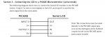
I don't want to use the optional clock so I am assuming I don't have to connect the other circuit board with the button battery holder on it. Right?

Now I am a little confused how I connect the LCD axe033.jpg to the picaxe/temp board.

It looks simple enough, but I can't even see on the LCD how to find the V+ and the 0V. Let alone the OUT and the IN. Sorry for the silly questions.

Any help would be appreciated.
Thanks
 

westaust55

Moderator
The LCD that you give a reference to is not an AXE033 module but just a "straight" LCD display which has a parallel communications connection.

The Rev Ed AXE033 module (datasheet here: http://www.rev-ed.co.uk/docs/axe033.pdf )
comprises a LCD module like the photo you reference PLUS a piggyback board which is a serial to parallel converter.
The hand drawing line from OUT 3 on the schematic you reference is then wired (along with the power connections) to the piggyback board on the AXE033 module.

Look at page 5 of the AXE033 datasheet for the electrical connections
 

jberries

New Member
Ohhhh ok, I thought the AXE033 was the LCD, oops I see.

So it looks like I DO have to connect (soldier) them together, the LCD is parallel, the AXE033 is serial.

I will give it a shot and report back. Many thanks westaust55

Also I think when you said OUT 3 you meant OUT 2.
 

westaust55

Moderator
I will give it a shot and report back. Many thanks westaust55

Also I think when you said OUT 3 you meant OUT 2.
Oops, yes the schematic does show it on OUT 2.

What I had in mind but though I would keep initial comments simple was:

As out 2 is already shown driving an LED you could connect the AXE033 module to OUT 3 (for example).
That way you could operate the LED on OUT 2 separate from the AXE033 LCD module which would be more versatile as there are a number of spare outputs available.
If you have some software that came with the project kit, the worste that you would have to do is change the pin number in the program (which is extremely easy to do - people on this forum can guide you if need be)
 
Last edited:

jberries

New Member
I think I have completely messed up my LCD/AXE033. I had to unsolder all the header pins, as I screwed something up. Now some of the circle terminals (that the header pins fit into) in the PCB and LCD have come adrift. Yikes. Might have wrecked it. Doh. (smacking forehead) Is this possibles to fix?
 
Last edited:

Andrew Cowan

Senior Member
All of the pads have wires going to them, which lead to other pads. Although you cannot solder to the pads that have broken off, you can solder to the other pads.

Where a pad has come off, follow its wire back until you come to another pad. Solder wire to this, and the other end of the wire to the header. Never put too much force on connections, or this kind of thing can happen.

Let us know how you get on fixing it!

Andrew

EDIT: Just noticed you said pads have come off on the LCD's PCB as well. While the other PCB is not too hard to fix, the LCD's PCB is going to be almost impossible to fix as the chips mounted on it already don't have visable pads. Especially if you are not the most tallented, you won't be able to repair the LCD's PCB.

Buy another and call it a good lesson? (But practice your soldering before it arrives)
 
Last edited:

Dippy

Moderator
I agree with Andrew even though I don't know what a 'pag' is :)

Yes, please learn lessons and also another couple of lessons spring to mind:-
1. Yes, practice soldering.
2. Triple check before soldering.
3. And it sounds like your soldering iron is a bit hot and/or you are holding on for ages. If you've managed to burn off double sided pads then phew! Did you get impatient and give everything a good old tug too?

Generally, when connecting SIL pin things it is sometimes a good idea to get SIL header pins and sockets. You can get them in lengths so you can cut to suit.
Yes, it'll cost you a quid but look what it can save.
Headers and sockets come in all sorts of configs. Well worth the cost.
 

hippy

Ex-Staff (retired)
I think I have completely messed up my LCD/AXE033. I had to unsolder all the header pins, as I screwed something up. Now some of the circle terminals (that the header pins fit into) in the PCB and LCD have come adrift. Yikes. Might have wrecked it. Doh. (smacking forehead) Is this possibles to fix?
It might be possible to fix as others have suggested. In the worse case, run flying wires from one PCB to the other. A fibreglass pencil-brush will often remove lacquer from a PCB and reveal a copper track which can be soldered to.

I've messed-up the same way on boards where components are stubborn, won't come out and physical force and prolonged heat causes this problem. Prolonged heat while sucking solder which won't budge out of a PTH can also cause the same.

A tip for removing a row of molex pins is to take some cutters and cut the plastic so each pin can be removed separately. Sometimes the plastic bar can be levered up and off the pins.

When trying to salvage a connector from a PCB which is going to be binned / recycled, dremmel / hacksaw the PCB so the PCB bits can be lifted away from one ( or few ) pins at a time. That can be a long, difficult, tortuous process so it's often easier to just buy the component you need.

Components and PCB's can be such effective heatsinks that it's almost impossible to remove some things.
 

westaust55

Moderator
Often the holes are also plated through. So even if the pad on the surface has been lifted due to excessive heat, some solder will still flow down into the hole.

So there is a small chance that soldering a pin into the holes may work.
Otherwise exposing some of the copper track to solder onto as other have suggested is your only chance.


Out of curiosity, precisely how did you get it "wrong"?
Its a one for one correspondence between the two boards.
 
Last edited:

Andrew Cowan

Senior Member
If you want to practice your soldering, try soldering resistors to stipboard (veroboard). What most people get wrong (from my experience), is they put the solder on the iron - not the heated joint between the component and board.

Andrew
 

jberries

New Member
Out of curiosity, precisely how did you get it "wrong"?
Yeah I was hoping no one would ask that :D , remember how I said I was a newbie :D, ... basically I soldered it all together and everything looked great. I also soldered the 4 OUT/V+/IN/0V to the AXE033 (not the LCD).
Tried it out and it didn't work.... I didn't see any obvious shorts on the pin header connections and the solder looked like it had taken.
Then it said "If you are using 4.5v batteries, then short circuit the J2 terminal. I thought it meant on the LCD, so awkwardly soldered the J2 on the LCD (sneaking the iron in between 2 boards).
Tried it out and it didn't work....
Realized that they meant J2 on the AXE033 and soldered that one.
Tried it out and it didn't work....
Then I thought the J2 on the LCD short circuit must be killing it..... thats when the fun began. Trying to remove that. At the time I thought the best way to remove it was to take the boards apart, looking back I probably wouldn't do it again.
Now I know someone here is going to say "Nope the J2 connection on the LCD was fine, you could have left that", but anyway it wass't working for me.

Thanks all for your responses, I will probably buy another one. Is the one I purchased the simplest :rolleyes: to get working?
 

westaust55

Moderator
No one is having a shot at you here. Just gives us an idea how we may be able to help.

I take it that you may also be new to electronics kits in general.
If so Andews advice on soldering practice would be worth following.

The AXE033 is a relatively easy to assemble and has both serial and I2c comms capability. If you go the way of another AXE033 then use header pins for all the connections even for the supply, comms and at jumpers locations J1 and J2. Then you can use some computer type jumper links when you want to bridge two points.

There are other LCD module that have larger displays like 4 x 20 (instead of 2 x 16). But the cost is greater as well.

I have both an AXE033 and a separate 4x20 module that came fully assembled with a serial comms already attached.

Where do you live (country). Someone in same region may be able to point you towards a fully assembled module available local to you.

If you take some clear close up photos to both sides of your existing AXE033 (both boards), we can have a look and see if some instructions can be given on how to fix it/get it going.
 

jberries

New Member
Hi westaust55, I just updated my location. I am in New Zealand. Looks like you are in Australia. Where did you purchase your assembled LCD/AXE033 from? I might be able to pick it up from the same place.
 

BCJKiwi

Senior Member
Take a look at PHAnderson's site. He has made up modules and freight is reasonable.

commands are slightly different however as it uses a different interface board from the Rev-Ed module.
 

westaust55

Moderator
The fully assembled LCD was not an AXE033 type.

It is a different make (RTN designed serial piggyback board) with a 4 x 20 character LCD module with backlight.

I bought it from Ron Nollet who runs an electronics/robotics business in Victoria

http://www.nollet.com.au/index.htm

Just had a look on his website and no sign of the LCD displays in the price list. You could always email him. Although predominantly a Parallax agent, Ron has been quite helpful for me with a few bit such as the LCD display and E-Labs keypad decoder chip.

BCJKiwi has also given you another option
 
Top