Audio spectrum analyzer schematics

MI6TUX

New Member
Hey all - great forum - got a lot from it, but would anyone have schematics or even just a rough plan for a good detailed spectrum analyzer - displaying on a GLCD - have a look at the video below for what I mean. Need a good analyzer to interface to a HF radio - they're extremely handy when trying to find stations among the noise, especially morse and data stations that are very narrowband.

http://www.youtube.com/watch?v=4PybPuqMfuk

Thanks and 73 DE MI6TUX!
 

Dippy

Moderator
I haven't Googled - that's your job, so I can only give you advice based on my experience.

I have done 2 Spectrum Analysers using FFT.
They used a PIC flat out and a dsPIC.
The dsPIC version could do a better job than shown on that video.
Sadly, it is well beyond PICAXE an a programming novice. Thousands of 'floating' calcs, variables* and piles of memory are required for 20 to 20kHz FFT.
There may be kits out there I haven't looked.

* I don't want to start an argument here, so I use 'variable' in the loose sense.
 

womai

Senior Member
I have developed and built an inexpensive Picaxe 28X1 based sampling oscilloscope. I will make the design freely available in the near future. See this thread:

http://www.picaxeforum.co.uk/showthread.php?t=9644

The associated scope software - written in VB6 and running on a PC - has an FFT mode which will produce a real-time frequency spectrum display very close to what you are after (one could easily extend the VB6 code to display the envelope as in the youtube example). That way the heavy data crunching is done on the PC and the limited computing power of a Picaxe is of no consequence. Analog bandwidth is about 400 kHz and max. sample rate is 1 MSample/sec, so audio spectrum display (i.e. from 20 Hz to about 20 kHz) is well within its capabilities. Sample record length is 256 samples, giving you a FFT frequency display with 128 bins. Screen refresh rate in FFT mode is about 3 frames/sec. The only thing it doesn't do is display on a GLCD, you do need the PC (or laptop) attached and it gets displayed on its monitor; not sure how important that is to you.

Wolfgang
 
Last edited:

MI6TUX

New Member
Many thanks for the replies. I've been Googling for weeks now but to no avail - I thought I'd ask the experts in the PICACE forum. Thanks, and I'll check those plans out. No problem with the PC interfacing - its a ham shack so it'll have about 6 computers in it at once, so that won't be a problem! ;)
Awesome build womai - i'll definitely check that out, and if you're selling the kits (I'm just reading the topic now - excuse me if you're not) it'd be easy to extent the code and run the output through a small LCD interfaced via serial to the PC. Thanks for everything!

73 DE MI6TUX
 

Dippy

Moderator
Sorry, I thought you meant a standalone device with GLCD.

If Wolfgang isn't flogging his excellent project (or you want it tomorrow) then consider the offerings from PICO and others - which have built-in FFT Spectrum Analysis.
 

LizzieB

Senior Member
I think I'm missing something...

If it follows an HF radio then the required audio bandwidth can't be very great, and if you are willing to use a PC to facilitate the display why not just use one of the many excellent sound card spectrum analyzer programs that are on the street?
 

moxhamj

New Member
Agree with LizzieB - this would be so useful that a dedicated PC would be worth considering. FFT calcs are much easier on a PC, but who knows, maybe we might get spoiled soon with a DSP picaxe with heaps of ram to store arrays and floating point maths and hardware multiplies.

Amazing to think what you get with a soundcard spectrum analyzer. I played with a dedicated hardware spectrum analyser in the early 90s when doing some bionic ear research and that machine was worth many tens of thousands of dollars.

The tracing was real time, and you could display in lots of different modes including colours. Some deaf people had got so skilled they could actually read speech looking at the FFT tracing.

womai's design sounds very useful. Any chance of publishing some/all of it?
 

womai

Senior Member
> womai's design sounds very useful. Any chance of publishing some/all of it?

Yes, I'll publish all. I just want to be sure everything works and is solid before putting it on the web.

This afternoon I just put together the second revision of the board - had to do it twice because the first PCB had a manufacturing defect (all others of the same batch were fine) that left a sizable area of copper that shouldn't have been there, shorting together power and ground and several other signals :mad: Of course I noticed that fault only AFTER I had assembled and soldered the complete circuit... On the upside, by now I can assemble and solder a complete scope in less than 90min.

The new version now has a real RS-232 port (using a MAX232) which will make it easier to port it to a native PIC when desired, because now it can use the hardware USART. Still a few Picaxe program issues to work out with that interface, my first attempt to use hserin instead of serrxd was only very moderately successful (meaning I received data, but not the one I sent :) although hserout works fine through the MAX232.

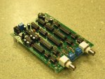
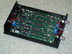
Other additions are through-hole BNC connectors and a power connector, so for people wanting to spend a minimum amount of money building it a bare-board version is usable (see first attachment). Of course an enclosure makes it look more professional and less geeky ;)

Cost for the bare-board version is around US$50 if you are careful and get about half of the chips as free samples (from Microchip and Maxim). This assumes you build your own PCB (e.g. protoboard) for less than $15, or I manage to get enough people interested to justify a larger batch order from ExpressPCB.

Wolfgang
 

Attachments

Last edited:

Dippy

Moderator
That looks really smart Wolfgang. Nice job.

Can you give a total cost (assuming people don't scrounge bits from Manufacturers)?

If I were you I would't assume massive sales via this Forum, so base your costs on a minimum practical production. Maybe 100 off? Dunno what the board size is exactly but I'd guess at 10 to 15USD each assuming d/s?

Time scale? If you are hoping for a 100off (even bumping your thread daily) then you could be waiting for months or are you hoping Rev-Ed will take it on? It's certainly a terrific project and simply down to cost. Be pepared for dozens of emails from newbies.. "It doesn't work...".

Will you support the PC software? (I can hear it now, "Will there be a version for Linux?" ;))

Drac: when I did FFT on a dsPIC I had 512 sample points and that was taking about half a sec to calculate a 10 to 10K spectrum (it was for my Doppler speed warning sign which I never finished). An interpreted language version would be a lot slower even assuming you were allowed hundreds of floating array elements.... don't hold your breath, but it would be nice.

Thinking aloud: Poor man's Spectrum Analysis. A PICAXE controlled swept band-pass filter?
A bit crude yes, but then so is FFT for doing even 40 to 3k with 256 samples.
This is a PIC version onto a GLCD with a 1.0kHz sine wave from a TTi Func gen:-
 

Attachments

MI6TUX

New Member
Hi,
I was hoping for a dedicated GLCD device - because I do a lot of mobile/portable work and it would be very handy to build a device that clamps onto the side of the radio, but I suppose something like an Eee PC would be fine. Thanks for all the replies. The bandwidth required isn't all that great, as you suggested, but for contests such as CQWW (CQ Worldwide) it would be so handy to have a good FFT display (the scope on the IC-7400 isn't in realtime like higher models like the IC-756 Pro3 or the IC-7700 or IC-7800, which have colour TFTs capable of high-resolution FFT display). I'll try to get the PC option working on the Eee PC, and have it shielded from RF (the Eee PCs dont seem to like HF being blasted into them) and maybe have a separate serial GLCD showing the display. An FFT really is a must in modern contest station.

Thanks, and 73 DE MI6TUX!
 
Top